- Home
- A-Z Catalogue
- Products
- Valves
- Cetop
- Manual Directional Valves
- Proportional Valves
- Poppet Valves
- High-Speed Linear Servo Valves
- All High-Speed Linear Servo Valves
- Cetop 10 (NG32) Two Stage Type High Speed Linear Servo Valves – LSVHG-10
- Cetop 10 (NG32) Two Stage Type High Speed Linear Servo Valves – LSVHG-10 (With Fail-Safe)
- Cetop 8 (NG25) Two Stage Type High Speed Linear Servo Valves – LSVHG-06
- Cetop 8 (NG25) Two Stage Type High Speed Linear Servo Valves – LSVHG-06 (With Fail-Safe)
- Cetop 7 (NG16) Two Stage Type High Speed Linear Servo Valves – LSVHG-04
- Cetop 7 (NG16) Two Stage Type High Speed Linear Servo Valves – LSVHG-04 (With Fail-Safe)
- Cetop 5 (NG10) Direct Type High Speed Linear Servo Valves – LSVG-03
- Cetop 5 (NG10) OBE Type Direct Operated Linear Servo Valves – LSVG-03-EH
- Cetop 3 (NG6) OBE Type Direct Operated Linear Servo Valves – LSVG-01-EH
- Pumps
- Pressure control
- Flow Control Valves
- Pressure Control Valves
- All Pressure Control Valves
- Brake Valves
- Direct Relief Valve
- Low Noise Solenoid Controlled Relief Valves
- Low Noise Pilot Operated Relief Valves
- Pilot Operated Relief Valves
- Pressure reducing and relieving valves
- Pressure reducing and check valves
- Pressure control valves
- Remote Control Relief Valves
- Solenoid Controlled Relief Valves – BSG
- Solenoid Controlled Relief Valves – BST
- Unloading relief valves
- Check valves
- Environmental
- Valves
- Hydraulic Systems
- Power pack
- About Us
- Contact
- Blog

How to Choose the Right Directional Control Valve
A directional control valve can look like a small part on a schematic, yet it determines where fluid moves, when an actuator responds, and how reliably a machine performs. Choosing one involves more than matching port sizes. Flow rate, operating pressure, spool configuration, actuation method, response time, and contamination tolerance all shape the decision. A valve that works smoothly on a test bench may behave differently in a warm cabinet beside a vibrating pump. Small details matter.
Fluid-power researcher Noah D. Manring has studied hydraulic system design. A useful paraphrase of the selection principle reflected in his work is: “Choose for the circuit, not the catalog.” That means checking the valve’s rated flow against real demand, confirming pressure limits, and tracing each port connection against the circuit diagram. It also means asking what happens during startup, load changes, or loss of electrical power. Pressure changes everything. A practical comparison should use manufacturer data sheets and documented operating conditions, not assumptions based on a product name. If the machine cycles slowly, response requirements may be modest; a fast-moving cylinder can demand a different choice. I’ll admit that selection is not always tidy. Catalog ratings can hide trade-offs, and one specification rarely tells the whole story. This guide explains how to compare valve types, read key ratings, and check compatibility before installation. The aim is a choice that fits the application—not merely one that fits the drawing.
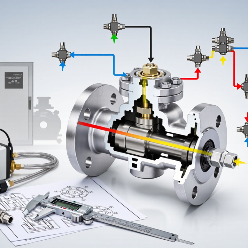
Table of Contents
[Hide]
Understanding the Function of a Directional Control Valve
A directional control valve decides where hydraulic fluid travels; it does not create pressure or flow. In a common four-way circuit, pressure enters port P, while ports A and B connect to opposite sides of a cylinder. Shifting the spool sends fluid to one side and opens the other toward tank, extending or retracting the rod. Small shift. A few millimeters of spool movement can change the actuator’s direction.
The center position matters. A closed-center spool blocks the ports, while a tandem-center design can return pump flow to tank; neither guarantees a load will stay perfectly still. Internal leakage, load, and circuit design affect the result. Check the schematic, pressure rating, flow capacity, and spool configuration together. Port labels alone can mislead.
The U.S. Department of Energy’s Improving Pumping System Performance sourcebook reports that pumping systems account for nearly 20% of global electricity demand. This is not a valve-specific statistic, but it highlights why avoidable pressure loss matters. A restrictive valve can convert useful hydraulic energy into heat. During selection, compare the required flow with the valve’s rated capacity, then check pressure drop under the actual operating conditions. The catalog figure is only a starting point.
Related Posts
-
What Is a Directional Control Valve?
-

2026 How to Choose a Hydraulic Relief Valve for Optimal Performance?
-
How to Choose the Right Hydraulic Valve in 2026?
-
7 Tips for Buying the Right Yuken Valve?
-
2026 Best Hydraulic Directional Control Valve for Sale?
-
Maximizing Efficiency: How Directional Control Valves Transform Hydraulic Systems