- Home
- A-Z Catalogue
- Products
- Valves
- Cetop
- Manual Directional Valves
- Proportional Valves
- Poppet Valves
- High-Speed Linear Servo Valves
- All High-Speed Linear Servo Valves
- Cetop 10 (NG32) Two Stage Type High Speed Linear Servo Valves – LSVHG-10
- Cetop 10 (NG32) Two Stage Type High Speed Linear Servo Valves – LSVHG-10 (With Fail-Safe)
- Cetop 8 (NG25) Two Stage Type High Speed Linear Servo Valves – LSVHG-06
- Cetop 8 (NG25) Two Stage Type High Speed Linear Servo Valves – LSVHG-06 (With Fail-Safe)
- Cetop 7 (NG16) Two Stage Type High Speed Linear Servo Valves – LSVHG-04
- Cetop 7 (NG16) Two Stage Type High Speed Linear Servo Valves – LSVHG-04 (With Fail-Safe)
- Cetop 5 (NG10) Direct Type High Speed Linear Servo Valves – LSVG-03
- Cetop 5 (NG10) OBE Type Direct Operated Linear Servo Valves – LSVG-03-EH
- Cetop 3 (NG6) OBE Type Direct Operated Linear Servo Valves – LSVG-01-EH
- Pumps
- Pressure control
- Flow Control Valves
- Pressure Control Valves
- All Pressure Control Valves
- Brake Valves
- Direct Relief Valve
- Low Noise Solenoid Controlled Relief Valves
- Low Noise Pilot Operated Relief Valves
- Pilot Operated Relief Valves
- Pressure reducing and relieving valves
- Pressure reducing and check valves
- Pressure control valves
- Remote Control Relief Valves
- Solenoid Controlled Relief Valves – BSG
- Solenoid Controlled Relief Valves – BST
- Unloading relief valves
- Check valves
- Environmental
- Valves
- Hydraulic Systems
- Power pack
- About Us
- Contact
- Blog

7 Tips for Buying the Right Yuken Valve?
Selecting the right yuken valve is a practical engineering decision, not merely a brand preference. A valve must match pressure, flow, fluid, temperature, mounting, and control requirements. One incorrect specification can create heat, noise, leakage, or unstable actuator movement. The U.S. Department of Energy identifies hydraulic systems as significant industrial energy users, making efficient component selection increasingly important. Small losses can become expensive across continuous production.
Market research also shows sustained demand for hydraulic equipment. MarketsandMarkets has reported that automation, mobile machinery, and industrial modernization continue driving hydraulic equipment adoption worldwide. These trends increase pressure on buyers to choose reliable, serviceable components. However, published market growth does not guarantee that every valve fits every circuit. That assumption needs questioning.
This guide presents seven practical tips for buying a yuken valve with greater confidence. It considers technical compatibility, operating conditions, response requirements, installation space, maintenance access, documentation, and total ownership cost. Yuken product catalogs and installation manuals should remain primary references, while ISO 4401 mounting standards can help verify interface compatibility. Manufacturer data matters.
A lower purchase price may look attractive. It may not remain economical after downtime, contamination, or seal replacement. Buyers should compare verified performance data, not just catalog headlines. Field experience also matters, especially where pumps cycle frequently or equipment operates near its pressure limit. Even experienced teams can overlook return-line restrictions or unsuitable fluid viscosity. That is an uncomfortable but useful reminder.
The following tips are designed for engineers, maintenance managers, and procurement teams. They support informed evaluation without replacing application-specific calculations or qualified technical advice.
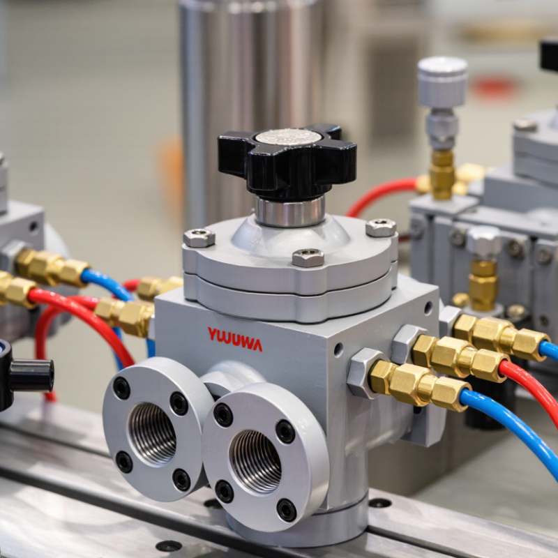
Table of Contents
[Hide]
Define the Hydraulic Application and Operating Conditions
Before choosing a hydraulic valve, define the application in measurable terms. Record pressure, flow, temperature, duty cycle, fluid type, and actuator size. A valve rated for 210 bar may perform poorly during pressure spikes. Check the real peak, not only the machine’s normal reading. ISO 4413 recommends evaluating hydraulic systems through operating conditions, risks, maintenance needs, and contamination control.
Flow behavior matters. A directional valve for a fast cylinder may require low pressure loss and reliable switching. A pressure-control valve may need stable response during sudden load changes. In field inspections, I have seen sizing errors create hot oil, noisy pumps, and slow actuators. The pipe was correct. The valve was not.
Energy also deserves attention. The International Energy Agency’s Energy Efficiency 2023 report states that industry consumes approximately 37% of global final energy. Small hydraulic losses can therefore become significant operating costs. Compare the valve’s rated flow with the required flow at the actual pressure. Review leakage limits, filtration, seal compatibility, and ambient temperature. The National Fluid Power Association also emphasizes application-specific sizing in its technical guidance.
Do not rely on catalog numbers alone. Test the machine at startup, steady load, and emergency stopping conditions. I once treated a brief pressure spike as unimportant. That assumption needed correction. A pressure trace, fluid sample, and cycle-time measurement often reveal more than a specification sheet.
Related Posts
-
2026 Top Yuken Valve Types for Global Buyers?
-
How to Choose the Right Hydraulic Valve in 2026?
-

Understanding the Role of Hydraulic Valves in Modern Industrial Applications
-
7 Essential Tips for Choosing the Right Hydraulic Valve for Your Application
-
How to Choose a Hydraulic Control Valve in 2026?
-
How to Choose a Hydraulic Pressure Control Valve?