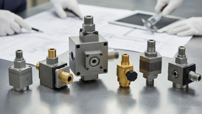
What Is a Directional Control Valve?

A directional control valve determines where hydraulic or pneumatic fluid flows, and when that flow changes. Its ports connect the pressure supply, actuator, and return path; its spool or poppet shifts to open, block, or redirect those connections. The result can be a cylinder extending, retracting, or holding position. Small component. Big effect. A blocked passage can stop motion, while an unsuitable valve can make an actuator respond slowly or unpredictably. The details matter.

Automation provides useful context. The International Federation of Robotics’ World Robotics 2024 report counted 4,281,585 industrial robots operating worldwide in 2023. That figure does not measure directional control valve use, but it reflects the scale of automated equipment that depends on controlled movement. ISO 1219-1:2012 standardizes fluid-power symbols used in circuit diagrams, while ISO 4413:2010 sets general safety requirements for hydraulic systems. These references help engineers interpret diagrams and consider system-level risks. They do not replace checking the actual machine, operating pressure, fluid, and duty cycle.

This article explains how directional control valves work, how common configurations differ, and what to examine when selecting one. A practical example is a valve shifting a cylinder that lifts a machine guard: port arrangement, flow capacity, and the actuator’s load all affect performance. Yet a specification sheet cannot tell the whole story. Installation, contamination, and maintenance can change real-world behavior. That part is easy to underestimate. The aim here is clear, useful guidance—not a claim that one valve fits every circuit.
What Is a Directional Control Valve?

Definition and Role of a Directional Control Valve

What Is a Directional Control Valve?

Definition and Role of a Directional Control Valve

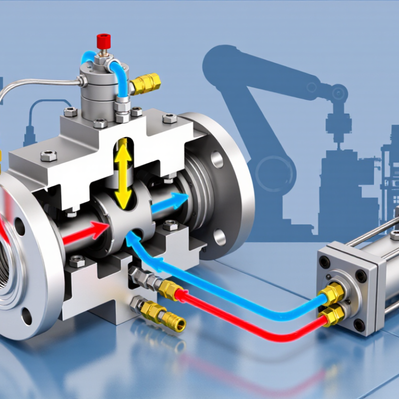
A directional control valve directs fluid through selected paths in a hydraulic or pneumatic circuit. It connects supply, actuator, and return ports to start, stop, or reverse movement. In a common hydraulic setup, a spool shifts inside the valve body, linking pressure to one cylinder port while opening the other to return. The cylinder extends. Shift the spool, and the flow path reverses. Some valves use poppets or solenoids instead; the operating principle remains controlled routing.

The valve’s role depends on its circuit and center position. A closed-center valve may block flow when idle, while an open-center design allows flow to continue. Port labels and mounting patterns matter. A small mismatch can cause unexpected motion or leakage. Not by itself. A directional valve does not automatically regulate actuator speed or guarantee that a load stays in place; other circuit components may be needed.

The U.S. Department of Energy’s Improving Pumping System Performance sourcebook reports that pumping systems account for nearly 20% of global electricity demand. That figure covers pumping systems broadly, not directional valves specifically, but it underlines why flow paths and pressure losses deserve attention.

In practice, valve selection should follow the required flow, pressure, actuator behavior, and operating conditions—not a port diagram alone. That distinction is easy to overlook.

How a Directional Control Valve Routes Fluid

A directional control valve guides fluid between a pump, a tank, and a working device such as a hydraulic cylinder. Its spool moves inside a close-fitting bore, opening some passages while blocking others. In a common four-port valve, P carries pressure in, T returns fluid to the tank, and A and B connect to the actuator. The labels describe ports, not fixed flow directions in every operating state.

Move the spool one way, and pressure may flow from P to A while fluid leaves B through T. The cylinder then extends. Shift the spool the other way, and P connects to B while A returns to T, retracting the cylinder. That sounds simple. It isn’t always. A valve’s center position can block ports, connect them to tank, or allow selected paths, depending on its design. Small passages, contamination, and pressure drops can also affect response. When checking a circuit, trace each spool position on its symbol and compare it with the actual port markings. I sometimes expect a diagram to tell the whole story; it doesn’t. The valve’s rated flow and operating pressure matter too.

Main Components and Valve Configurations

What Is a Directional Control Valve?
Main Components and Valve Configurations

A directional control valve guides hydraulic fluid between a pump, actuator, and reservoir. Inside its body, a sliding spool or poppet opens and closes flow paths. Lands on the spool seal selected passages; springs often return it to a default position. The actuator may be manual, electrical, hydraulic, or pneumatic. Small clearances matter. Contamination or wear can cause leakage, sluggish movement, or sticking. ISO 4406:2021 classifies hydraulic-fluid cleanliness using particle counts at three thresholds: 4, 6, and 14 μm(c). It is a useful maintenance measure, though it cannot diagnose every valve fault.

Valve configurations are described by the number of ports and switching positions. A 4/3 valve, for example, has four ports and three positions: typically pressure, tank, and two actuator ports. ISO 1219-1:2012 provides standardized symbols for reading these arrangements in circuit diagrams. In the center position, a closed-center spool blocks the ports; a tandem center connects pressure to tank while blocking the actuator ports. Other center designs allow actuator ports to drain or connect more freely. Details vary by circuit. The symbol helps, but it does not show response time, leakage, or pressure limits. Fit matters. A technically correct valve can still perform poorly if its flow capacity or center condition mismatches the cylinder and pump.

What Is a Directional Control Valve? - Main Components and Valve Configurations

Category Component or Configuration Purpose or Flow Behavior Typical Details
Function Directional control valve Starts, stops, or changes the direction of fluid flow to control an actuator. Used in hydraulic and pneumatic circuits; valve selection depends on the fluid, pressure, flow, and circuit requirements.
Main component Valve body Houses the internal moving element and provides the fluid passages and connection ports. Port layout and mounting style vary by valve design.
Main component Spool or poppet Moves to open, block, or connect flow paths. Spool valves use a sliding spool; poppet valves use a seating element. Not every valve uses both types.
Main component Actuator or operator Applies force to shift the spool or poppet. Common methods include manual lever, mechanical input, solenoid, pneumatic pilot, and hydraulic pilot operation.
Main component Return spring Returns a spring-loaded valve element toward its default position when the actuating force is removed. Some valves use two springs, detents, or other position-retaining arrangements instead.
Main component Seals and end covers Help limit external leakage and contain or guide internal components. Materials and construction are selected for the fluid, temperature, and operating conditions.
Valve notation Ports and positions The first number in common notation indicates the number of ports; the second indicates the number of switching positions. For example, a 4/3 valve has four ports and three positions.
Configuration 2/2 valve Opens or blocks a flow path between two ports. Often used for basic on/off control; available in normally open or normally closed forms.
Configuration 3/2 valve Switches one working port between a pressure or supply port and an exhaust or return port. Commonly used to control a single-acting cylinder or provide a pneumatic signal.
Configuration 4/2 valve Switches pressure and return connections between two work ports. Provides two operating positions, commonly for reversing a double-acting actuator.
Configuration 4/3 valve Reverses flow to a double-acting actuator and provides a third, center position. The center position determines how the ports behave when the valve is centered.
Center condition Closed center Blocks the main ports in the center position. Can hold an actuator in position, but leakage and load-holding requirements must be considered.
Center condition Open center Connects the main ports in a way that allows flow through the valve in the center position. Exact port connections depend on the valve’s spool pattern.
Center condition Tandem center Typically connects pressure to tank while blocking the work ports in the center position. Often used in circuits where the pump needs an unloaded flow path while the actuator is held.
Center condition Float center Typically connects both work ports to tank while blocking the pressure port. Allows an actuator to move more freely under an external load, subject to circuit design.

Common Types of Directional Control Valves

A directional control valve decides where hydraulic fluid travels, when it moves, and which actuator responds. In practice, technicians identify valves by their ports and switching positions. A 2/2 valve opens or blocks one path. A 3/2 valve can supply and exhaust a single-acting cylinder. These compact arrangements are common in basic on-off tasks.

Four-way valves handle more complex motion. A 4/2 valve switches flow to extend or retract a double-acting cylinder. A 4/3 valve adds a center position, which may block, release, or connect flow paths. That center setting matters: the wrong choice can let a load drift or leave a pump working against resistance. Solenoid, manual, and pilot actuation are common; selection depends on response needs and available controls.

Spool designs offer flexible port routing, while poppet designs can provide tight shutoff. Proportional directional valves vary flow as their electrical command changes, rather than switching only between fixed positions. The U.S. Department of Energy’s 2006 sourcebook, Improving Pumping System Performance, estimates pumping systems use nearly 20% of global electricity. That figure is not valve-specific. Still, it makes pressure drop and correct sizing worth measuring. One imperfect detail: catalog labels do not always reveal how a valve behaves under real load.

Applications and Key Selection Factors

What Is a Directional Control Valve?

Applications and Key Selection Factors

A directional control valve routes hydraulic or pneumatic fluid, starting, stopping, or reversing an actuator. In a lift, it directs oil to raise the platform, then releases flow for lowering. In a factory press, its switching pattern helps control cylinder movement. These valves do not regulate pressure by themselves; confusing those functions can lead to a poor specification.

Selection starts with the circuit: a 4/3 valve may serve a double-acting cylinder, while a 3/2 valve suits a single-acting actuator. Check rated pressure and flow, then account for pressure drop at the actual operating flow. The U.S. Department of Energy’s Improving Pumping System Performance sourcebook reports that pumping systems use nearly 20% of global electricity, and 25–50% of energy in some industrial operations. That figure covers pumping systems, not directional valves specifically. Still, it underlines why unnecessary throttling deserves attention. Small losses add up.

Also consider response time, duty cycle, fluid compatibility, contamination tolerance, and the required fail position if power is lost. A valve that works on a clean test bench may behave differently in a dusty mobile machine. Confirm the port arrangement and actuator type against the circuit diagram, and check filtration requirements against the valve manufacturer’s technical documentation. That detail is easy to miss. Selection is rarely just about matching a port size; real operating conditions may expose trade-offs the initial specification overlooked.