10 Best Hydraulic Units for Industrial Buyers

Choosing among the 10 best hydraulic units for industrial buyers requires more than comparing pressure ratings. A unit may look capable on paper, yet struggle with long duty cycles, heat, or frequent start-stop operation. The U.S. Department of Energy’s Improving Pumping System Performance: A Sourcebook for Industry reports that pumping systems use nearly 20% of global electricity. That figure covers pumping broadly, not hydraulic power units alone. Still, it shows why efficiency deserves attention.

In practical terms, buyers should compare rated flow, operating pressure, reservoir capacity, motor efficiency, filtration, cooling, and control options. Picture a press running through repeated cycles on a warm factory floor: undersized cooling or poor fluid cleanliness can turn a small specification gap into unplanned downtime. The right hydraulic unit should match the machine’s real operating profile, not just its peak demand. Details matter.

This guide considers products through measurable specifications, industrial use cases, serviceability, and manufacturer documentation. It also distinguishes standard features from options, since configurations can vary by market and application. No shortlist replaces checking a supplier’s current datasheet or confirming compatibility with the driven equipment. That trade-off is easy to miss. Buyers should verify pressure and flow at the required duty cycle, then assess noise, maintenance access, and parts support. A ranking can guide research, but it cannot predict every plant condition.
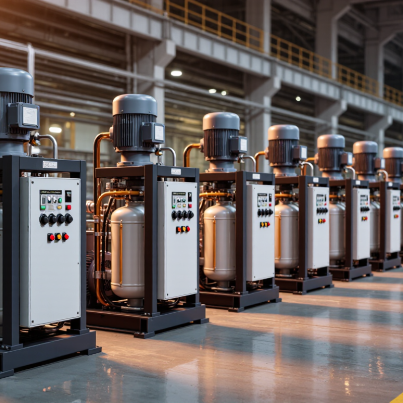
10 Best Hydraulic Units for Industrial Buyers

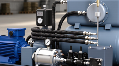
Hydraulic Power Units Explained: Pumps, Reservoirs, Motors, and Valves

A hydraulic power unit converts mechanical energy into controlled fluid power. Its pump sets flow, while system pressure depends on the load and circuit resistance. A fixed-displacement pump can suit steady operations; variable-displacement designs may reduce wasted flow in changing duty cycles. Neither choice is automatically better. Match pump capacity to actuator speed, pressure needs, and operating hours.

The reservoir stores oil, releases heat, and gives air and contaminants time to separate. Look beyond tank volume: check access for cleaning, return-line placement, and room for thermal expansion. An undersized reservoir may run hot during repeated cycles. A larger tank is not a cure-all. The electric motor must provide enough power for the pump at the required pressure, with suitable starting capacity and protection from dust or moisture.

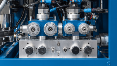
Valves direct flow, limit pressure, and control motion. A relief valve protects components, while directional and flow-control valves shape actuator movement. For example, a lift table may need smooth lowering, not just high lifting force. Specify filtration and service access too; a clogged filter can quietly restrict flow. In practice, selection charts help, but they rarely capture every duty cycle or installation detail. Measure the real load and cycle rate where possible. A few assumptions may still be wrong, so leave room to verify them during commissioning.

Sizing by Pressure and Flow: Hydraulic HP = PSI × GPM ÷ 1,714

Hydraulic horsepower is estimated with a simple relationship: PSI × GPM ÷ 1,714. Pressure describes the force available; flow determines how quickly an actuator moves. For example, a system delivering 2,000 PSI at 10 GPM requires about 11.7 hydraulic horsepower. That is the calculated power in the fluid, not the motor’s full nameplate requirement. At 85% overall efficiency, the drive may need roughly 13.7 horsepower. Check the pump and motor specifications before choosing a unit.

The numbers must represent pressure and flow available at the same time. A pump may reach its rated pressure at low flow, so adding separate maximum ratings can mislead. Measure operating conditions at the intended duty point, including pressure losses through hoses, valves, and filters. Leave capacity for startup loads and heat management, but avoid oversizing without a reason. Too much flow can waste energy and raise fluid temperature. A little margin helps. Still, efficiency varies with load, temperature, and component wear; the formula is a starting point, not a complete design. I still find that distinction easy to overlook when comparing units.

10 Hydraulic Unit Sizing Examples

Theoretical hydraulic horsepower by operating pressure and flow rate

Hydraulic horsepower is calculated as PSI × GPM ÷ 1,714. Values are theoretical hydraulic output; actual motor input requirements are higher because of pump and system losses.

10 Best Hydraulic Units by Duty Cycle, Flow Rate, and Application

For a useful “best” list, rank hydraulic units by operating pattern, not headline pressure. A 24/7 production line needs a continuous-duty unit with cooling sized for sustained heat. A press that runs in short bursts may suit an intermittent-duty unit with an accumulator. Other practical candidates include variable-speed units for changing demand, high-flow units for rapid motion, compact units for clamping, low-noise units for indoor machinery, mobile units for field equipment, servo-hydraulic units for precise testing, redundant units for critical lines, and simple fixed-displacement units for steady loads. The U.S. Department of Energy’s Improving Pumping System Performance sourcebook reports that optimized pumping systems can often save 20–50% of pumping energy. That range is not a guaranteed saving for every hydraulic power unit.

Flow and pressure must be checked together. A common estimate is hydraulic power in kilowatts = pressure in bar × flow in litres per minute ÷ 600, before accounting for losses. For example, 100 bar at 60 litres per minute requires about 10 kW of hydraulic output. Check motor capacity, heat rejection, filtration, and duty cycle against the real operating profile. ISO 4406 classifies fluid cleanliness using particle counts at 4, 6, and 14 micrometres. Small contamination matters. A unit that looks oversized on paper may still run hot if it spends hours near relief pressure. Conversely, buying extra flow “just in case” can waste energy. There is no perfect ranking; logged pressure and flow data make the shortlist more dependable.

10 Best Hydraulic Units for Industrial Buyers — By Duty Cycle, Flow Rate, and Application

This is a general selection guide to common hydraulic power-unit configurations, not a ranking of specific products. Flow and pressure ranges are typical planning ranges and vary by design. Confirm the required flow, operating pressure, motor rating, cooling capacity, and duty cycle with the equipment manufacturer before selection.

Hydraulic Unit Type Typical Duty Cycle Typical Flow Rate Typical Working Pressure Best-Fit Applications Key Selection Consideration
Compact intermittent-duty power unit Short operating bursts with extended rest periods 2–15 L/min (0.5–4.0 US gpm) 70–210 bar (1,000–3,000 psi) Small lifting tables, access platforms, compact presses, and equipment with occasional movement Check motor starting frequency and oil-temperature rise during repeated cycles.
Mobile-equipment power unit Intermittent to moderate; dependent on vehicle operating pattern 5–30 L/min (1.3–7.9 US gpm) 140–250 bar (2,000–3,625 psi) Vehicle-mounted lifts, tail lifts, service equipment, and small material-handling systems Consider available electrical supply, vibration, enclosure protection, and mounting orientation.
General-purpose industrial power unit Intermittent to frequent cycling 10–60 L/min (2.6–15.9 US gpm) 100–250 bar (1,450–3,625 psi) Machine tools, fixtures, small production presses, and general factory automation Match pump displacement to the actuator speed and account for simultaneous movements.
Continuous-duty power unit with cooling High utilization or continuous operation when properly sized 20–80 L/min (5.3–21.1 US gpm) 100–250 bar (1,450–3,625 psi) Production lines, continuous material handling, and process equipment Size the reservoir and heat exchanger for the system’s actual power losses and ambient temperature.
High-flow power unit Frequent or continuous operation, depending on cooling and pump design 40–160 L/min (10.6–42.3 US gpm) 70–210 bar (1,000–3,000 psi) Large cylinders, fast machine cycles, and systems requiring high actuator speed Confirm motor power, suction-line sizing, filtration capacity, and acceptable pressure drop.
High-pressure clamping power unit Intermittent or cyclic clamping operation 2–20 L/min (0.5–5.3 US gpm) 250–350 bar (3,625–5,075 psi), where components are rated accordingly Workholding, clamping circuits, and specialized pressing applications All hoses, valves, cylinders, and fittings must be rated for the maximum system pressure.
Accumulator-assisted power unit Brief peak-flow demands with periods for accumulator recharge 5–30 L/min (1.3–7.9 US gpm) pump flow; short-term delivered flow may be higher 100–250 bar (1,450–3,625 psi) Rapid clamping, short press strokes, and circuits with occasional peak demand Accumulator sizing, pre-charge, isolation, and safe pressure-release provisions are essential.
Variable-speed, demand-controlled power unit Frequent cycling with variable or changing demand 5–80 L/min (1.3–21.1 US gpm), depending on motor and pump selection 70–250 bar (1,000–3,625 psi) Automated machinery and systems with variable flow requirements or significant idle periods Check drive compatibility, control response, cooling at low speed, and required peak flow.
Dual-pump high-low power unit Intermittent press or clamping cycles with rapid approach and slower working stroke Combined approach flow commonly 20–100 L/min (5.3–26.4 US gpm); high-pressure flow is lower Typically 100–250 bar (1,450–3,625 psi), subject to component ratings Presses and machines that need fast unloaded travel followed by a slower force-producing stroke Verify the unloading or changeover pressure and ensure the high-pressure pump meets the working-stage demand.
Corrosion-resistant washdown power unit Intermittent to continuous, depending on thermal design and enclosure 10–50 L/min (2.6–13.2 US gpm) 70–210 bar (1,000–3,000 psi) Food-processing areas, washdown zones, and environments exposed to moisture or cleaning chemicals Specify suitable materials, seals, electrical enclosure protection, and fluid compatibility for the cleaning environment.

Compare Fixed- and Variable-Displacement Units by Energy Use and Control

For industrial buyers, the right hydraulic unit depends on how demand changes across a shift. A fixed-displacement unit delivers a steady flow whenever its pump runs. It is straightforward to specify and can suit equipment with consistent cycles, such as a conveyor lift operating at one speed. But when the machine idles or needs less flow, excess oil may pass through a relief valve, creating heat and wasting energy.

A variable-displacement unit adjusts output to match demand. On a press that pauses between strokes, this can reduce unnecessary flow and motor load. It can also support closer control of speed and pressure, though the result depends on correct sizing, setup, and maintenance. More control means more to get right.

Check operating pressure, duty cycle, fluid temperature, and the number of hours spent at partial load before comparing options. Ask suppliers for measured power or efficiency data at your actual operating points, not only at peak output. In practice, one detail is easy to miss: a variable unit may cost more upfront, while savings depend on how often demand falls below full capacity. A noisy test run or unexpectedly warm reservoir deserves investigation, not guesswork.

Specify Oil Filtration with ISO 4406 Cleanliness Codes and Micron Ratings

A hydraulic unit’s filter should be specified by the cleanliness its components require, not by micron rating alone. ISO 4406 reports particle counts at 4, 6, and 14 µm(c), using three numbers. Lower numbers indicate fewer particles in each size range. For instance, a target such as 18/16/13 gives buyers and maintenance teams a shared way to discuss oil cleanliness. Check component documentation before setting that target; a pump and a servo valve may have different needs.

Micron ratings describe which particle sizes a filter captures, but the rating method matters. Ask whether the figure is nominal or absolute, and request the beta ratio at the stated particle size. A 10-micron label alone does not tell you enough. Consider flow rate, oil viscosity, operating pressure, and cold starts, too. A filter that restricts flow can trigger bypass or increase pressure drop. Small details, real consequences.

Confirm cleanliness with a properly collected oil sample, ideally under consistent operating conditions. Sampling from a stagnant drain can distort the result. New oil is not always clean enough for a demanding system, either. In practice, this is where specifications get messy: handling, storage, and filter changes can introduce contamination after the unit is commissioned. Set a cleanliness target, document the sampling point, and review trends alongside filter condition.