


- Home
- A-Z Catalogue
- Products
- Valves
- Cetop
- Manual Directional Valves
- Proportional Valves
- Poppet Valves
- High-Speed Linear Servo Valves
- All High-Speed Linear Servo Valves
- Cetop 10 (NG32) Two Stage Type High Speed Linear Servo Valves – LSVHG-10
- Cetop 10 (NG32) Two Stage Type High Speed Linear Servo Valves – LSVHG-10 (With Fail-Safe)
- Cetop 8 (NG25) Two Stage Type High Speed Linear Servo Valves – LSVHG-06
- Cetop 8 (NG25) Two Stage Type High Speed Linear Servo Valves – LSVHG-06 (With Fail-Safe)
- Cetop 7 (NG16) Two Stage Type High Speed Linear Servo Valves – LSVHG-04
- Cetop 7 (NG16) Two Stage Type High Speed Linear Servo Valves – LSVHG-04 (With Fail-Safe)
- Cetop 5 (NG10) Direct Type High Speed Linear Servo Valves – LSVG-03
- Cetop 5 (NG10) OBE Type Direct Operated Linear Servo Valves – LSVG-03-EH
- Cetop 3 (NG6) OBE Type Direct Operated Linear Servo Valves – LSVG-01-EH
- Pumps
- Pressure control
- Flow Control Valves
- Pressure Control Valves
- All Pressure Control Valves
- Brake Valves
- Direct Relief Valve
- Low Noise Solenoid Controlled Relief Valves
- Low Noise Pilot Operated Relief Valves
- Pilot Operated Relief Valves
- Pressure reducing and relieving valves
- Pressure reducing and check valves
- Pressure control valves
- Remote Control Relief Valves
- Solenoid Controlled Relief Valves – BSG
- Solenoid Controlled Relief Valves – BST
- Unloading relief valves
- Check valves
- Environmental
- Valves
- Hydraulic Systems
- Power pack
- About Us
- Contact
- Blog

What Is the Best Hydraulic Power Pack from China?
Choosing the best hydraulic power pack from China requires more than comparing prices or browsing polished product photos. A reliable unit must match the machine’s pressure, flow, duty cycle, motor rating, and installation space. In practical use, a small mismatch can cause slow cylinder movement, excessive heat, or repeated downtime. The right hydraulic power pack should perform steadily in workshops, mobile equipment, lifting systems, and automated production lines.
China offers a wide range of manufacturers, from specialized hydraulic workshops to large industrial suppliers. Their products may include compact DC power units, AC-driven systems, custom valve blocks, and high-pressure assemblies. However, quality is not identical across every factory. A professional evaluation should examine material selection, pump efficiency, reservoir welding, filtration, sealing quality, and tested operating pressure. Ask for technical drawings, inspection records, and clear warranty terms. Factory experience matters.
Details reveal quality.
For example, clean internal pipework, labeled ports, and protected electrical connections often indicate careful assembly. A supplier that explains maintenance intervals is usually more trustworthy than one promising only the lowest quotation. Still, no manufacturer is perfect. Documentation may be incomplete, delivery estimates can change, and a sample unit may perform better than a larger batch. This deserves attention.
This guide compares leading selection factors, supplier credibility, customization ability, testing procedures, and long-term service. It also considers total ownership costs, not just the initial purchase price. By reviewing these points carefully, buyers can identify a hydraulic power pack that offers dependable performance, practical maintenance, and safer integration into their equipment.
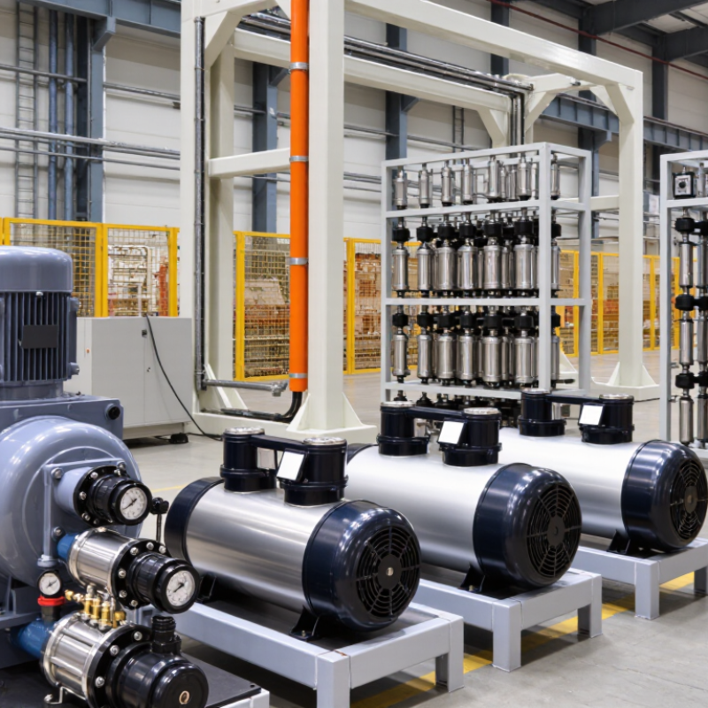
Table of Contents
[Hide]
What Is a Hydraulic Power Pack and How Does It Work?
A hydraulic power pack is a compact system that supplies pressurized fluid to hydraulic equipment. It usually contains a reservoir, electric motor, hydraulic pump, valves, filters, and pressure protection. The motor turns the pump, and the pump moves oil through the circuit. The pump creates flow, while resistance creates pressure. Pressure comes from the workload.
When an operator activates a control valve, fluid travels toward a cylinder or hydraulic motor. The cylinder may lift a platform, clamp a component, or move a machine arm. Return fluid flows back into the reservoir. A relief valve opens when pressure rises beyond the safe setting. This protects hoses, seals, and actuators from excessive stress. Clean oil matters. Even small particles can damage precision valve surfaces.
Choosing the best hydraulic power pack from China requires more than comparing prices. Confirm the required flow rate, working pressure, motor voltage, tank capacity, and installation space. Ask for pressure testing, electrical inspection records, material details, and replacement-part support. A lower-cost unit may appear attractive, but an undersized pump can overheat during repeated cycles. That mistake is common. In my view, dependable performance comes from correct sizing and documented quality control, not country of origin alone. Some specifications still need checking under real operating temperatures, because laboratory results may not reflect a dusty workshop or frequent start-stop use.
| Evaluation Dimension | Hydraulic Power Pack Type or Specification | How It Works | Typical Technical Data | Suitable Applications | Selection Considerations |
|---|---|---|---|---|---|
| Basic Function | Hydraulic power pack | An electric motor or engine drives a hydraulic pump, which converts mechanical energy into pressurized hydraulic fluid. The fluid then moves an actuator or hydraulic motor. | Reservoir, pump, prime mover, valves, filters, pressure-relief protection, and control components are commonly integrated into one compact assembly. | Lifting, clamping, steering, material handling, industrial machinery, mobile equipment, and compact automation systems. | Choose the unit according to required pressure, flow, duty cycle, actuator size, installation space, and control method. |
| Power Source | AC electric motor | Electrical energy drives the hydraulic pump through a motor and coupling. | Common industrial motor ratings include approximately 0.25–30 kW; three-phase motors are widely used for continuous industrial duty. | Factory equipment, presses, machine tools, loading systems, and indoor installations. | Check voltage, frequency, phase, motor enclosure, starting current, and thermal protection. |
| Power Source | DC electric motor | A battery or vehicle electrical system powers a compact DC motor connected to the hydraulic pump. | Common systems use 12 V or 24 V DC; 48 V configurations are also used in selected mobile and industrial applications. | Tail lifts, wheelchair lifts, mobile platforms, small dump bodies, and battery-powered equipment. | Battery capacity, cable size, motor duty cycle, maximum current, and protection against voltage drop are important. |
| Pump Type | External gear pump | Meshing gears carry hydraulic fluid from the inlet to the outlet and generate flow against system resistance. | Compact and economical; commonly used for moderate flow and pressure applications. Typical efficiencies are lower than those of piston pumps. | General industrial machinery, lifting systems, agricultural equipment, and simple hydraulic circuits. | A practical choice where cost, compact size, and straightforward maintenance are more important than very low noise or maximum efficiency. |
| Pump Type | Vane pump | Sliding vanes in a rotating rotor transport fluid through the pump chambers. | Provides smoother flow and generally lower noise than a basic gear pump; suitable for moderate pressure applications. | Industrial power units, machine tools, plastic-processing equipment, and systems requiring smoother operation. | Requires clean hydraulic oil and proper inlet conditions to reduce vane wear and cavitation risk. |
| Pump Type | Axial piston pump | Rotating pistons reciprocate inside a cylinder block to deliver pressurized hydraulic fluid. | High pressure capability, high efficiency, and fixed- or variable-displacement configurations are available. | High-force equipment, injection machinery, mobile machinery, test systems, and demanding industrial applications. | Higher initial cost and greater sensitivity to contamination make filtration, oil quality, and maintenance especially important. |
| Pressure Range | Low-pressure power pack | The pump supplies fluid pressure adequate for low-force actuation and circulation tasks. | Usually below approximately 100 bar, depending on the circuit and component ratings. | Small clamps, light-duty lifting mechanisms, lubrication systems, and low-force automation. | Do not select a low-pressure unit when the actuator must overcome high loads or shock conditions. |
| Pressure Range | Medium-pressure power pack | Pressurized oil is directed through valves to generate moderate actuator force and speed. | Approximately 100–250 bar is common for many general-purpose hydraulic systems. | Material handling, compact presses, lifting platforms, agricultural machinery, and industrial automation. | Verify the continuous working pressure, peak pressure, relief-valve setting, and cylinder load requirements. |
| Pressure Range | High-pressure power pack | A high-pressure pump delivers oil to actuators that require substantial force from a compact system. | Approximately 250–350 bar is used in many high-pressure applications; actual limits depend on component design. | Heavy-duty presses, hydraulic tools, compact construction equipment, and high-force clamping systems. | Every component, hose, fitting, valve, and reservoir connection must be rated for the intended pressure and safety margin. |
| Flow Rate | Low-flow configuration | The pump supplies a small volume of oil per minute, typically prioritizing compact size and controlled movement. | Approximately 0.5–5 L/min is common for small actuators and precise low-speed movement. | Small lifting devices, compact clamps, medical or accessibility equipment, and light automation. | Lower flow generally reduces actuator speed; confirm cylinder displacement and required cycle time. |
| Flow Rate | Medium-flow configuration | The pump provides a balance between actuator speed, motor size, heat generation, and reservoir capacity. | Approximately 5–30 L/min is common for general-purpose power units. | Machine tools, industrial lifting systems, mobile equipment, and medium-sized actuators. | Calculate flow from actuator area and target speed, then check motor power and thermal performance. |
| Flow Rate | High-flow configuration | A larger-displacement or multi-pump arrangement supplies sufficient oil for rapid or multiple actuator movement. | Above approximately 30 L/min; larger systems may require increased motor power, cooling, and reservoir volume. | Large presses, rapid-cycle machinery, multiple hydraulic circuits, and heavy mobile equipment. | Evaluate pressure-flow combinations carefully because hydraulic power and heat generation increase with both parameters. |
| Valve Configuration | Single-acting circuit | Hydraulic pressure moves the actuator in one direction, while a spring, gravity, or external load provides return movement. | Usually uses one pressure port and a return or tank connection; valve selection depends on load-holding requirements. | Dump bodies, lifting tables, jacks, clamps, and simple lifting applications. | Confirm that the load can return the actuator safely and that lowering speed can be controlled. |
| Valve Configuration | Double-acting circuit | Hydraulic pressure is directed alternately to both sides of the actuator for controlled extension and retraction. | Commonly uses a directional control valve with two work ports and a pressure-relief valve. | Hydraulic cylinders, positioning systems, steering mechanisms, presses, and automated machinery. | Consider valve center condition, actuator synchronization, load holding, and required cycle speed. |
| Reservoir Capacity | Compact reservoir | The tank stores enough fluid for a small circuit while keeping the power pack lightweight and space efficient. | Approximately 1–10 L is common for small intermittent-duty systems. | Portable tools, compact lifts, small clamps, and limited-cycle equipment. | Allow adequate fluid volume for cylinder displacement, thermal expansion, deaeration, and safe minimum level. |
| Reservoir Capacity | Standard industrial reservoir | The reservoir stores and cools hydraulic oil while allowing air and contaminants to separate from the fluid. | Approximately 10–100 L is common, although the required size depends on flow, duty cycle, and heat load. | Industrial machinery, lifting equipment, presses, and continuous or repeated-cycle applications. | Tank sizing should account for return-flow aeration, heat dissipation, maintenance access, and fluid expansion. |
| Control Method | Manual control | An operator activates a lever, hand valve, or push-button control to direct hydraulic flow. | Simple wiring and valve arrangements; suitable for applications with direct operator supervision. | Service equipment, basic lifts, maintenance tools, and low-volume machinery. | Cost effective, but it may not provide the repeatability or remote monitoring available with electronic controls. |
| Control Method | Solenoid or PLC control | Electrical signals operate directional valves and can be integrated with sensors, switches, or a programmable controller. | Supports automated sequences, interlocks, position feedback, and remote operation. | Production lines, automated presses, packaging machinery, and coordinated motion systems. | Check voltage, connector protection, control logic, emergency-stop requirements, and electromagnetic compatibility. |
| Efficiency and Heat | Fixed-displacement system | The pump delivers a fixed volume per revolution; excess flow is commonly bypassed through a relief or unloading circuit. | Simple and economical, but throttling and bypass flow can generate heat during extended operation. | Intermittent-duty equipment and applications with relatively stable flow demand. | Use suitable cooling, unloading, or accumulator arrangements when operating continuously under high pressure. |
| Efficiency and Heat | Variable-displacement system | The pump adjusts displacement to match system demand, reducing unnecessary flow and energy consumption. | Higher efficiency potential and better control of power consumption, with increased system complexity. | High-duty-cycle machinery, variable-speed applications, and systems with changing flow requirements. | Higher purchase cost may be justified when energy savings, lower heat generation, and precise control are priorities. |
| Reliability | Filtration and contamination control | Filters remove particles from the hydraulic fluid before contamination damages pumps, valves, and actuators. | Filter ratings are specified in micrometres and may include suction, pressure-line, and return-line filtration. | All hydraulic systems, especially high-pressure and servo-controlled equipment. | Use clean oil, correct filter ratings, proper breathers, and scheduled filter replacement to extend component life. |
| Safety | Pressure-relief protection | A relief valve limits system pressure by diverting fluid when pressure exceeds its set value. | Relief settings must remain within the lowest rated pressure of the pump, valves, hoses, cylinders, and fittings. | Essential for virtually every hydraulic power pack. | Never block or improperly adjust the relief valve; use guarding, emergency stops, and safe maintenance procedures. |
| Best-Fit Criteria | Recommended specification for a general-purpose unit | A balanced configuration combines an appropriately sized motor, gear or vane pump, relief protection, filtration, reservoir, and directional valve. | Typical starting range: 12–24 V DC or 400 V three-phase motor, 5–30 L/min flow, and 100–250 bar working pressure, subject to application calculations. | General lifting, clamping, material handling, and medium-duty industrial machinery. | The best power pack is not determined by origin alone; it should be selected through verified pressure-flow performance, component compatibility, testing, documentation, service support, and compliance with applicable safety requirements. |
Related Posts
-
The Essential Guide to Understanding Hydraulic Power Packs in Industrial Applications
-
How to Choose the Right Hydraulic Unit for Your Industrial Needs
-

Top Hydraulic Unit Trends to Watch in 2025 for Optimal Performance
-

Why You Should Invest in a Hydraulic Unit for Efficient Machinery Operation
-
What is a Hydraulic Power Pack and How Does it Work?
-
How to Choose the Right Hydraulic Unit for Your Needs?





