- Home
- A-Z Catalogue
- Products
- Valves
- Cetop
- Manual Directional Valves
- Proportional Valves
- Poppet Valves
- High-Speed Linear Servo Valves
- All High-Speed Linear Servo Valves
- Cetop 10 (NG32) Two Stage Type High Speed Linear Servo Valves – LSVHG-10
- Cetop 10 (NG32) Two Stage Type High Speed Linear Servo Valves – LSVHG-10 (With Fail-Safe)
- Cetop 8 (NG25) Two Stage Type High Speed Linear Servo Valves – LSVHG-06
- Cetop 8 (NG25) Two Stage Type High Speed Linear Servo Valves – LSVHG-06 (With Fail-Safe)
- Cetop 7 (NG16) Two Stage Type High Speed Linear Servo Valves – LSVHG-04
- Cetop 7 (NG16) Two Stage Type High Speed Linear Servo Valves – LSVHG-04 (With Fail-Safe)
- Cetop 5 (NG10) Direct Type High Speed Linear Servo Valves – LSVG-03
- Cetop 5 (NG10) OBE Type Direct Operated Linear Servo Valves – LSVG-03-EH
- Cetop 3 (NG6) OBE Type Direct Operated Linear Servo Valves – LSVG-01-EH
- Pumps
- Pressure control
- Flow Control Valves
- Pressure Control Valves
- All Pressure Control Valves
- Brake Valves
- Direct Relief Valve
- Low Noise Solenoid Controlled Relief Valves
- Low Noise Pilot Operated Relief Valves
- Pilot Operated Relief Valves
- Pressure reducing and relieving valves
- Pressure reducing and check valves
- Pressure control valves
- Remote Control Relief Valves
- Solenoid Controlled Relief Valves – BSG
- Solenoid Controlled Relief Valves – BST
- Unloading relief valves
- Check valves
- Environmental
- Valves
- Hydraulic Systems
- Power pack
- About Us
- Contact
- Blog

Top Types of Directional Valves for Industrial Buyers
A directional valve decides where hydraulic or pneumatic energy travels. In a factory, that choice can affect cylinder motion, cycle time, and safe machine behavior. The right valve is not simply the one with the highest pressure rating. Buyers need to match its flow capacity, port arrangement, actuation method, and operating conditions to the circuit. A small mismatch can show up as slow motion, excess heat, or an actuator that stops short.
Fluid-power author Anthony Esposito’s work offers a useful selection principle. Paraphrased, not a verbatim quotation: “Choose the valve for the circuit’s flow paths and operating demands, not its catalog label alone.” That idea guides this overview of common directional valve types, including spool and poppet designs, solenoid-operated models, and manual or pneumatic options. Each suits different control needs. Some switch quickly; others favor simple, direct operation. Details matter. Buyers should also check pressure drop, contamination tolerance, response time, and maintenance access. A specification sheet cannot reveal every installation problem. This guide helps industrial buyers compare valve designs, ask better questions, and avoid treating a familiar product name as proof of suitability.
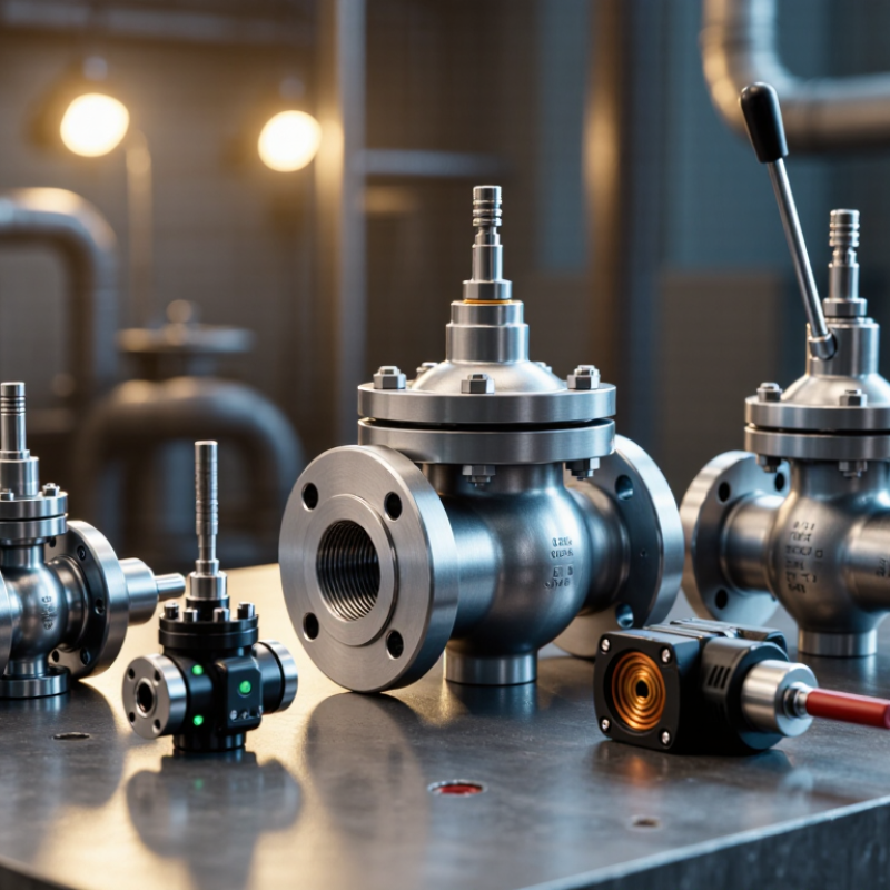
Table of Contents
[Hide]
How Directional Valves Control Fluid Flow
Directional valves control fluid flow by connecting the pressure, actuator, and return ports in selected patterns. Inside a spool valve, sliding lands open some passages while blocking others. A 4/3 valve, for example, can extend, stop, or retract a cylinder. Its center position determines what happens when the actuator pauses. A neat schematic can still hide a poor real-world match.
Valve choice affects more than motion. Port size, flow capacity, response time, and pressure drop all matter. The U.S. Department of Energy’s Improving Pumping System Performance: A Sourcebook for Industry reports that pumping systems can consume 25–50% of electricity in some industrial facilities. That figure describes entire systems, not valves alone. Still, excessive throttling at a directional valve can generate heat and waste energy. Measure operating flow and pressure under load, not just from a catalog.
Tips: Match valve flow capacity to the actuator’s actual demand. Check the center condition on 4/3 valves, then verify it during a safe bench test. Listen for chatter. Feel for unexpected heat, but use suitable temperature instruments; touch alone is unreliable.
Top Types of Directional Valves for Industrial Buyers – How Directional Valves Control Fluid Flow
| Valve type | Typical configuration | How it controls flow | Common actuation | Typical industrial uses | Buyer considerations |
|---|---|---|---|---|---|
| 2/2-way shut-off valve | Two ports, two positions; normally closed or normally open | Opens or blocks a single flow path. | Solenoid, manual, mechanical, or pneumatic | On/off control, isolation, and fluid supply switching | Check the required normal state, medium compatibility, and permitted leakage. |
| 3/2-way valve | Three ports, two positions; commonly supply, actuator, and exhaust | Connects the actuator port to supply in one position and to exhaust in the other, depending on valve design. | Solenoid, manual, mechanical, or pneumatic | Single-acting pneumatic cylinders and pilot signal control | Confirm normally open or closed operation and the correct exhaust arrangement. |
| 4/2-way directional valve | Four ports, two positions; typically pressure, tank, and two actuator ports | Alternates the pressure and return connections to reverse actuator movement. | Solenoid, manual, hydraulic pilot, or pneumatic pilot | Reversing double-acting cylinders or hydraulic motors | Match porting, flow capacity, pressure rating, and actuator requirements. |
| 4/3-way directional valve | Four ports, three positions; center condition may be closed, open, tandem, or float | Selects either direction of actuator flow, with a center position that determines what happens when the valve is neutral. | Manual lever, solenoid, hydraulic pilot, or proportional actuation | Hydraulic equipment requiring forward, reverse, and neutral control | Select the center condition carefully; it affects actuator holding and pump flow paths. |
| Spool-type valve | Sliding spool shifts between machined flow paths; available in multiple port and position arrangements | Spool lands open, close, or connect ports as the spool moves. | Manual, solenoid, pneumatic, or hydraulic pilot | General-purpose pneumatic and hydraulic circuit control | Review internal leakage, contamination tolerance, response, and mounting standard. |
| Poppet-type directional valve | A seat-and-poppet element opens or closes one or more flow paths | Moves a sealing element away from or onto its seat to switch flow. | Solenoid, pneumatic, hydraulic pilot, or mechanical | Applications requiring tight shut-off or fast switching, depending on design | Check allowable pressure differential, flow direction, switching behavior, and seal compatibility. |
Note: Port count, flow capacity, pressure rating, leakage, and available actuation vary by valve design. Confirm the manufacturer’s technical data and applicable system requirements before selection.
Related Posts
-
What Is a Directional Control Valve?
-
How to Choose the Right Directional Control Valve
-
How to Choose the Right Directional Control Valve for Your Project
-
7 Essential Tips for Choosing the Right Hydraulic Valve for Your Application
-
How to Choose a Hydraulic Control Valve in 2026?
-
How to Choose a Hydraulic Pressure Control Valve?