What Is a Pilot Operated Check Valve and How Does It Work?

A pilot operated check valve holds a hydraulic load in place, then releases it when pilot pressure arrives. Picture a raised cylinder carrying a steel plate: if supply pressure disappears, the valve helps prevent the load from dropping. When a controlled signal reaches its pilot port, the valve opens the return path. The result depends on pressure, oil condition, valve sizing, and correct installation. Small parts. Serious consequences.

Herbert E. Merritt, author of Hydraulic Control Systems, is a recognized reference in fluid-power engineering. His work supports a key design principle: hydraulic control depends on managing pressure and flow together. That sentence is a paraphrase, not a verified direct quotation. For industry context, Grand View Research’s Hydraulic Equipment Market Size report tracks demand across hydraulic machinery and equipment, while ISO 4413 sets general safety requirements for hydraulic fluid-power systems. Neither source replaces application-specific calculations or manufacturer guidance.

This guide explains the valve’s internal parts, pilot-pressure sequence, and common circuit uses. It also highlights failure points, including leakage, contamination, and incorrect pressure settings. A pilot operated check valve is not a universal fix for every load-holding problem. That deserves a closer look. In practice, technicians should confirm the circuit diagram, load direction, operating pressure, and release conditions before selecting or troubleshooting a valve. The physical details matter: a blocked pilot line or a worn seat can change how reliably a cylinder holds.
What Is a Pilot Operated Check Valve and How Does It Work?

Definition and Purpose of a Pilot-Operated Check Valve

A pilot-operated check valve is a one-way hydraulic valve that blocks reverse flow until a pilot signal opens it. In its resting state, pressure from the load presses a poppet or similar element against its seat. Oil can enter from the permitted direction, but it cannot readily return through the valve. That matters. For example, a cylinder supporting a raised platform can retain its position when pump pressure stops.

When the machine needs the cylinder to move back, pressure applied through a pilot line pushes the valve element off its seat. Return flow can then pass through the valve. The pilot pressure needed depends on the valve design and load conditions, so the circuit must be sized carefully.

A common mistake is to treat this as a simple shutoff valve; it is not. It relies on a separate control pressure to release the load-holding function. If the pilot signal is inadequate, movement may be slow or fail to occur.

If a load drifts, checking the valve alone may not reveal the cause; leakage elsewhere in the circuit can also matter.

Key Components and Their Functions

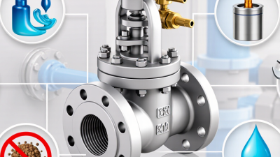
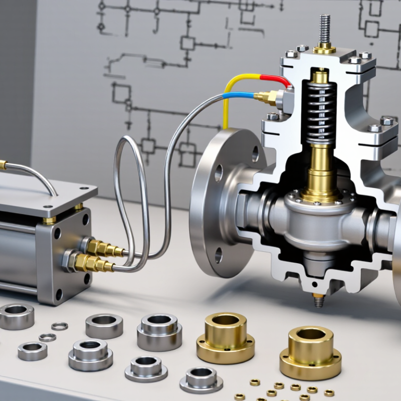
A pilot operated check valve combines a one-way check valve with a pilot mechanism. Its housing contains the working passages, while a poppet or ball seals against a seat to stop reverse flow. A spring usually presses the sealing element into place when pilot pressure is absent. That seal helps hold a hydraulic load, such as a raised cylinder, in position.

The pilot piston is the part that makes controlled release possible. When pressure reaches the pilot port, the piston moves and pushes the main poppet away from its seat. Fluid can then return through the valve, allowing the cylinder to move. Small passages guide the pilot pressure, and seals limit leakage around moving parts. The details vary by design.

That matters during troubleshooting. A blocked pilot line may keep the valve closed, even when the main circuit is pressurized. Dirt on the seat can cause drift. A valve can still leak. Check the pressure rating, pilot ratio, and circuit layout before selecting or adjusting one; back pressure can change how reliably it opens.

What Is a Pilot Operated Check Valve and How Does It Work?

Key Components and Their Functions

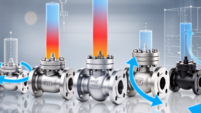
A pilot operated check valve uses pilot pressure to shift a pilot piston, which allows the main check element to open and release held hydraulic fluid. When pilot pressure is removed, the main element reseats to help prevent reverse flow. The chart shows conceptual component states, not measured test data; 0 means inactive or seated, and 1 means actuated or open.

How the Valve Opens, Closes, and Holds Pressure

A pilot operated check valve holds a hydraulic cylinder in position by blocking reverse flow. In the free-flow direction, oil lifts the main poppet or spool from its seat. Reverse pressure pushes it shut. To release the load, pilot pressure acts on a small control piston and overcomes the closing force. The pilot-to-load pressure relationship depends on the valve’s pilot ratio and circuit geometry.

Small details matter.

For example, a 3:1 pilot ratio is a design illustration, not a universal setting. Too little pilot pressure may leave the valve closed; excessive pressure can cause abrupt movement. ISO 4413:2010 sets safety principles for hydraulic systems, including control of pressure and unexpected motion.

Clean oil also supports reliable operation: ISO 4406:2021 code 18/16/13 corresponds to particle-count ranges of 1,300–2,500 per millilitre above 4 μm(c), 320–640 above 6 μm(c), and 40–80 above 14 μm(c). These figures describe cleanliness codes, not a required target for every circuit.

A restricted pilot passage can delay opening, while seat wear may allow slow drift.

That is easy to miss. Test the valve under the actual load, pressure, and oil-temperature conditions; a bench check alone may not reveal a stubborn, heat-related leak.

Common Configurations and Operating Conditions

A pilot-operated check valve holds a cylinder or other actuator in position until pilot pressure opens the valve. In a single-acting configuration, pressure from a separate line releases the load-holding port. A dual pilot-operated check valve controls both actuator ports, allowing the cylinder to be held in either direction. These arrangements are common in lifting and clamping circuits, where a drifting load can create a real safety concern.

Operating conditions matter as much as configuration. Check the maximum working pressure, flow rate, fluid type, and temperature against the valve’s specifications. Pilot ratio affects how much pressure is needed to release the valve; a high ratio may reduce pilot demand but can make operation more sensitive to load pressure. Long hoses, trapped pressure, or a rapidly moving load can also affect release behavior. The practical choice is not always obvious, so test the circuit under its expected load. A valve that holds well at rest may still release unevenly.

Tips: Confirm the pilot line reaches the correct port, and inspect fittings for leaks. Use clean, compatible fluid. During commissioning, raise and lower the load slowly, watching for drift or chatter. If movement feels abrupt, review the circuit design rather than assuming the valve alone is at fault.

Typical Applications and Selection Considerations

A pilot-operated check valve holds a hydraulic cylinder in position until pilot pressure opens the valve. It is useful where a suspended or clamped load must not drift when the control lever returns to neutral. Typical uses include lift platforms, presses, agricultural machinery, and material-handling equipment. On a lift, for example, the valve can help keep a loaded platform raised if the pump stops. That matters.

Selection starts with the circuit, not just the valve’s rated pressure. Check working pressure, peak flow, pilot ratio, cracking pressure, and allowable leakage against the actuator and load. Too high a pilot ratio may release a load abruptly; too low may require more pilot pressure than the system provides. Confirm whether the valve needs an external drain, especially where return-line pressure can trap the pilot piston. The U.S. Department of Energy’s 2015 Bandwidth Study on Energy Use and Potential Energy Saving Opportunities in U.S. Manufacturing estimates motor-driven systems use about 68% of manufacturing electricity. That figure is not specific to hydraulic valves, but it underscores why efficient, well-matched pump circuits matter. Also review fluid cleanliness and operating temperature. A selection can look right on paper and still behave poorly in a real circuit; that detail is easy to miss.

What Is a Pilot Operated Check Valve and How Does It Work? - Typical Applications and Selection Considerations

Category Typical Situation How the Valve Works Key Selection Considerations
Basic function A hydraulic actuator must hold position when supply flow stops. A spring-loaded check element permits flow in the free-flow direction and blocks reverse flow. Pressure applied to a pilot port acts on an internal piston to release the check element and allow controlled reverse flow. Confirm the required free-flow direction, pilot-port arrangement, operating pressure range, and whether the valve is intended for the circuit’s load-holding duty.
Single-acting cylinder load holding A cylinder supports a load that could move under gravity or an external force. A check valve installed in the relevant cylinder line can prevent oil from flowing back out of the cylinder. A pilot signal from the opposing circuit releases the valve when movement is commanded. Locate the valve close to the actuator where practical. Check load pressure, required lowering control, pilot pressure availability, and the consequences of hose or line failure.
Double-acting cylinder Both cylinder ports need to be blocked to hold the actuator in either direction. A dual pilot-operated check arrangement can block flow from both cylinder ports. Pressure in one work line pilots open the check in the opposite line, allowing the cylinder to move. Verify the valve’s porting and pilot connections against the circuit diagram. Consider cylinder area ratio, trapped pressure, thermal expansion, and the effect of load-induced pressure on the opposite line.
Vertical or suspended loads A raised platform, lift, or other actuator must resist an unintended downward movement. The valve restricts reverse flow from the actuator until a pilot signal opens it. It can help hold a load, but it is not a substitute for a mechanical safety device where one is required. Assess load-induced pressure, lowering stability, pressure surges, and leakage. For load control, select a circuit and valve arrangement suitable for the application rather than relying on a check valve alone.
Clamping and workholding A hydraulic clamp or fixture must maintain pressure while the directional control valve is neutral. The check element blocks reverse flow from the actuator. A pilot signal opens the valve when the circuit commands release or repositioning. Consider allowable actuator drift, required release behavior, cycle frequency, fluid cleanliness, and whether pressure loss elsewhere in the circuit could affect clamping force.
Pilot ratio and opening behavior The available pilot pressure must open the valve against pressure acting on the load side. The pilot piston helps overcome the force holding the check element shut. A higher pilot ratio generally reduces the pilot pressure needed to open, but may make the valve more sensitive to pressure changes. Compare the valve’s stated pilot ratio and opening requirements with actual pilot pressure under operating conditions. Account for load pressure, return-line back pressure, spring force, and pressure losses.
Flow capacity and pressure drop The actuator must move at the required speed without excessive restriction or heating. Flow passes through the valve’s check element in the free-flow direction and through the opened valve during pilot-controlled reverse flow. Size for the expected flow in both directions. Review rated flow, pressure drop, maximum working pressure, and the manufacturer’s operating limits for the intended fluid and temperature.
Fluid, mounting, and circuit compatibility The valve is being integrated into a new or existing hydraulic system. Different designs may be installed inline, on a manifold, or directly at an actuator port. Porting and internal construction affect how the pilot and working lines must be connected. Check fluid type and viscosity, seal compatibility, temperature range, connection size, mounting orientation, contamination-control requirements, and the circuit schematic before installation.

Note: Operating limits and opening behavior vary by valve design. Confirm sizing and circuit suitability using the selected valve’s technical data and the hydraulic system requirements.