What Is a Pilot Operated Check Valve and How Does It Work?
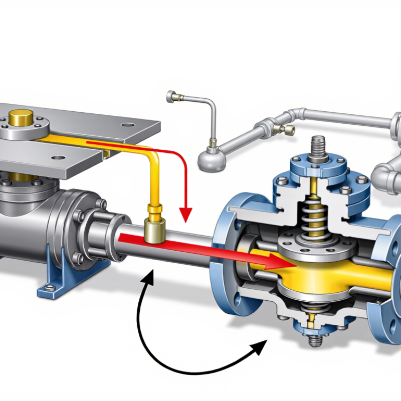
A pilot operated check valve holds a hydraulic load in place, then releases it when a pilot signal arrives. Imagine a raised cylinder supporting a steel plate. If the pump stops, the valve helps prevent oil from flowing backward and the plate from drifting down. That simple function matters in presses, lifting equipment, and machine tools.
Hydraulic author Anthony Esposito is known for explaining fluid-power systems in practical terms. Rather than present an unverified quotation as his exact words, this introduction summarizes the principle associated with his field: “Control the flow, and you control the motion.” The wording here is a paraphrase, not a direct quotation.
Inside the valve, a check element blocks flow in one direction. Pilot pressure acts on a piston or poppet, overcoming the force that keeps the element seated. The valve then opens, allowing reverse flow from the actuator. When pilot pressure disappears, the element closes again. It sounds straightforward. Real circuits are less tidy. Load pressure, pilot ratio, trapped air, and line restrictions can change how smoothly the valve releases. A poorly matched valve may cause slow movement or sudden load shifts. That detail is easy to overlook. Understanding the valve’s function is only part of choosing one safely; its pressure rating, installation orientation, and compatibility with the circuit also matter.
Pilot-Operated Check Valves: Definition and ISO 4413:2010 Context
What Is a Pilot Operated Check Valve and How Does It Work?
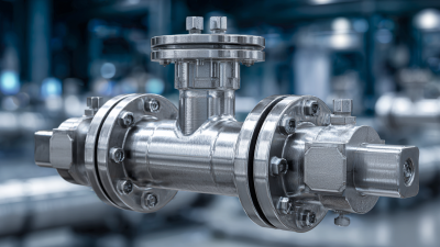
A pilot-operated check valve permits hydraulic fluid to flow freely in one direction and blocks reverse flow. A pilot signal can release that lock. When pressure reaches the pilot port, it shifts an internal piston or poppet, allowing fluid to return through the valve. Without sufficient pilot pressure, the valve stays closed and helps hold a cylinder or other loaded actuator in position. The exact pressure needed depends on the valve design and circuit conditions.
Pilot-Operated Check Valves: Definition and ISO 4413:2010 Context
ISO 4413:2010 sets safety requirements for hydraulic fluid power systems and their components. In practice, a pilot-operated check valve should be selected and installed as part of a considered circuit, not treated as a stand-alone safety guarantee. Designers need to account for working pressure, load, pilot pressure, trapped fluid, and the consequences of leakage or unexpected movement. A valve may hold a load during normal operation, yet poor sizing or installation can undermine that function. It is easy to assume the symbol tells the whole story; it does not. Check the applicable standard text and the valve’s technical documentation for the intended application.
Key Components: Poppet, Seat, Spring, and Pilot Port
What Is a Pilot Operated Check Valve and How Does It Work?
A pilot operated check valve holds hydraulic fluid in a cylinder until pilot pressure opens the valve. Its poppet is a small moving element that blocks flow when seated. The seat provides the sealing surface, often a precise ring inside the valve body. A spring presses the poppet against that seat when pilot pressure is absent. In this state, reverse flow is restricted, helping a loaded cylinder stay in position. Not perfectly, always: contamination, wear, or poor installation can affect sealing.
When pressure enters the pilot port, it acts on the poppet or an internal piston, depending on the design. That force overcomes the spring and moves the poppet away from the seat. Fluid can then return through the valve. The required pilot pressure depends on the valve’s pilot ratio, spring force, and load pressure; check the technical data rather than guessing. A weak or unstable pilot signal may cause slow release or chatter.
Tips: Keep the pilot line clear and use clean fluid. Before installation, confirm the flow direction and pressure rating. A tiny scratch on the seat can matter. If the load drifts, inspect the seat and poppet, but also consider cylinder leakage elsewhere.
How Pilot Pressure Opens the Valve: Typical 3:1–4:1 Pilot Ratios
What Is a Pilot Operated Check Valve and How Does It Work?
A pilot operated check valve holds a hydraulic load by blocking reverse flow. Pilot pressure opens the valve when the system needs movement. A common pilot ratio is 3:1 or 4:1. This ratio compares the effective pilot area with the area resisting the load pressure. With a 3:1 ratio, pilot pressure can theoretically overcome a load pressure about three times higher. Actual performance depends on valve design, pressure losses, and operating conditions.
For example, a cylinder supporting a raised platform may stay locked when the pump stops. When pressure reaches the pilot port, it shifts an internal piston and unseats the check element. Oil can then return through the valve, allowing controlled lowering. Higher ratios generally need less pilot pressure, but they may also make the valve more sensitive to pressure changes. The trade-off deserves attention.
Tips: Check the valve’s rated ratio and operating-pressure range, then compare them with the real load and available pilot pressure. Test movement under controlled conditions. Trapped pressure, long hoses, or a changing load can affect how smoothly the valve opens. A calculation helps, but it does not replace checking the actual circuit.
What Is a Pilot Operated Check Valve and How Does It Work? — How Pilot Pressure Opens the Valve: Typical 3:1–4:1 Pilot Ratios
A pilot operated check valve allows free flow into a hydraulic actuator and blocks reverse flow until pilot pressure is applied. The examples below show how a typical pilot ratio relates to the pressure needed to release the valve.
Illustrative pilot-pressure requirements
Pilot Ratio
Load Pressure at Actuator
Ideal Pilot Pressure to Open
How to Interpret the Example
3:1
90 bar
Approximately 30 bar
The load pressure is divided by the nominal ratio: 90 ÷ 3 = 30 bar.
3:1
150 bar
Approximately 50 bar
A higher load pressure requires more pilot pressure to release the check element.
4:1
90 bar
Approximately 22.5 bar
The larger ratio reduces the ideal pilot pressure needed for the same load pressure.
4:1
150 bar
Approximately 37.5 bar
Calculated as 150 ÷ 4; actual opening pressure may be higher.
3:1–4:1
200 bar
Approximately 50–67 bar
The range reflects the ideal calculation for ratios of 4:1 and 3:1, respectively.
Note: These are simplified estimates, not valve ratings. Actual pilot pressure depends on the valve’s construction, spring force, pressure on the opposite actuator port, line losses, and operating conditions. The pilot ratio describes the effective area relationship; consult the valve manufacturer’s technical data and system design requirements before selecting or setting a valve.
Pressure Holding and Leakage: Poppet-Seated Versus Spool-Type Designs
A pilot operated check valve holds a hydraulic actuator in position by blocking flow until pilot pressure shifts its internal element. When a directional valve sends pressure to the pilot port, that pressure helps lift the poppet or move the spool. Oil can then return through the valve. With the pilot signal removed, the valve closes again. The exact response depends on pilot pressure, load, and valve condition.
Poppet-seated designs press a sealing element against a seat, much like a plug closing a small opening. They generally provide tighter load holding than spool-type designs, which rely on close-fitting surfaces and may allow more internal leakage. Even a poppet can leak if debris scores its seat or the seal wears. A spool may suit applications where smooth flow matters more than near-static holding, but gradual cylinder drift can be frustrating. Neither design is perfect.
Tips: Check the specified leakage rate and pilot ratio, then test with the actual fluid and load. Watch the actuator over several minutes; a tiny movement may reveal more than a quick pressure reading. Keep ports clean during installation. Also, don’t assume a valve alone makes a suspended load safe—system design and maintenance still matter.
Pilot-Operated Check Valves: Pressure Holding Over Time
Conceptual comparison under a constant load with no pilot pressure applied. The traces illustrate typical design behavior, not measured performance; actual leakage depends on valve design, condition, fluid, and test conditions.
A seated poppet generally provides tighter shutoff because pressure pushes the sealing element against its seat. A spool-type design relies on close-clearance fits, so internal leakage may allow pressure to decay. Pilot pressure shifts the valve open, permitting flow in the reverse direction.
Selection Checks: Rated Pressure, Flow, and Manufacturer Specifications
A pilot operated check valve can hold a cylinder in position when the main supply line loses pressure. Before selecting one, check the rated pressure against the highest pressure the circuit may actually reach, including short spikes. A valve rated too close to the normal operating pressure may wear faster or fail to seal reliably. Leave a sensible margin, but follow the equipment designer’s limits.
Flow matters too. Compare the valve’s rated flow with the actuator’s required flow, and check the pressure drop at that rate. An undersized valve can slow a cylinder and generate heat; an oversized one may add cost without improving performance. Small details matter. Verify the pilot ratio and pilot pressure range, then confirm the port size and mounting style match the circuit. The spec sheet should state test conditions, leakage limits, and compatible fluid types. Read the fine print.
Manufacturer specifications are useful, but they do not replace checking the actual application. Record the load, operating temperature, expected cycle rate, and hose arrangement before ordering. A long pilot line, for example, can delay valve release. I have seen selection decisions based on pressure alone; that shortcut is tempting, and not always wise. When data is missing or unclear, ask for the test basis rather than guessing.