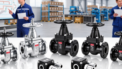
What Are the Types of Yuken Directional Valves?

A Yuken directional valve determines where pressurized oil travels, which actuator moves, and when that movement stops. The range can seem confusing at first. A valve’s name may describe its operation, its spool arrangement, or both. A useful starting point is to classify each model by its number of ports and positions, its actuation method, and its intended flow capacity.

Fluid-power author Anthony Esposito’s engineering guidance can be paraphrased this way: “Choose a directional valve for the circuit’s required flow path and operating conditions, not by its label alone.” This is a paraphrase, not a verbatim quotation. It reflects a practical point: a solenoid-operated valve may suit a control panel, while a manually operated model may fit a simpler machine. Pilot-operated designs can serve circuits with different flow demands. Details matter.

This guide examines the main types of Yuken directional valves, including common spool configurations and actuation options. It also explains how to read model information and compare pressure, flow, and mounting requirements. Picture a valve mounted beside a pump, with hoses feeding a cylinder: a mismatched center condition or connection can change how that cylinder behaves. Catalogs help, but they do not replace checking the actual circuit. Some selections still require careful review. The distinctions are useful, though not always obvious.
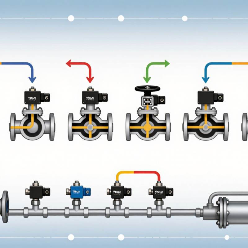
What Are the Types of Yuken Directional Valves?

How Yuken Directional Valves Control Hydraulic Flow

How Directional Valves Control Hydraulic Flow

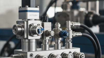
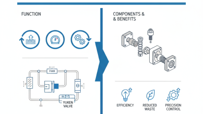
A directional valve routes pressurized oil between the pump, actuator, and tank. Inside the body, a sliding spool opens and closes precise passages. In a four-way valve, shifting the spool can send oil to one cylinder port while connecting the other port to return. Reverse the spool, and the cylinder changes direction. Small shift. Big effect.

The spool’s position also shapes flow behavior. A closed-center neutral position blocks the main passages, while an open-center design lets oil return to the tank. Some spool edges meter flow during movement, but the valve’s main job is routing—not precise speed control. An engineer should check the circuit design before blaming a slow cylinder. A pressure drop may come from a clogged filter or weak pump instead.

Clean oil matters. ISO 4406:2021 classifies hydraulic-fluid cleanliness using particle counts at 4, 6, and 14 micrometers (c) per milliliter. Those measurements help maintenance teams set contamination targets and compare oil samples. Yet a cleanliness code alone cannot diagnose wear. Check operating pressure, spool movement, and leakage together; field conditions rarely behave as neatly as a schematic.

Classification by Valve Configuration and Number of Ports

Directional valves are classified by configuration and port count. Configuration describes the number of spool positions and the flow paths available in each position. A 4/3 valve, for example, has four ports and three positions. Its center position may block all ports, connect selected ports, or allow the pump line to unload. Small symbols matter. Check the hydraulic schematic, not just the valve label. ISO 1219-1 provides standardized symbols for reading these flow paths, while ISO 5598 defines terminology used in fluid-power systems.

Port count identifies the valve’s connections: pressure, tank, and one or more actuator lines. A 2-way valve controls one flow path; a 3-way valve commonly serves a single-acting actuator; and a 4-way valve can direct flow to both sides of a double-acting actuator. A 2024 Grand View Research market report estimated the global hydraulic-valves market at about USD 5.2 billion in 2023, reflecting the broad industrial use of these components. That figure covers multiple valve types, not directional valves alone. In practice, match port count, spool positions, center condition, flow rating, and mounting interface to the circuit. Port numbers can look straightforward. They are not always intuitive on the machine. A mislabeled line can change actuator behavior.

Yuken Valve Types by Operating Method

Directional valves can be classified by the method that moves their internal element. Manual models use a lever or hand knob, giving operators direct control at the machine. Mechanical models use a cam, roller, or plunger, so movement follows a physical cycle. Solenoid-operated valves use an electrical signal for remote switching. Pilot-operated valves use hydraulic or pneumatic pressure to shift a larger main stage. Proportional valves vary the opening with the input signal, allowing smoother control than simple on/off switching.

The distinction matters during selection. A hand lever suits a nearby test bench; a solenoid may fit a guarded machine needing remote commands. Pilot operation can shift high-flow stages, but it adds control lines and setup requirements. I still find it easy to oversimplify: actuation method alone does not determine response, flow capacity, or stability. Those depend on the full circuit and valve specifications.

The U.S. Department of Energy’s 2006 Improving Pumping System Performance sourcebook reports that pumping systems use nearly 20% of global electricity, and 25–50% of energy in some industrial operations. That figure concerns pumping systems, not directional valves alone. It does underline why switching losses, pressure drop, and control strategy deserve attention during circuit design.

Key Design Features and Performance Differences

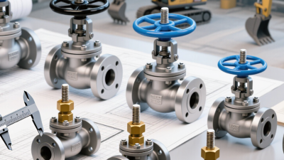
Directional valves differ by closure element, actuation, and mounting pattern. Spool designs route oil through several ports and support multiple switching positions. They are versatile, but clearance leakage can rise as parts wear. Poppet designs seat against an orifice, often limiting leakage when closed; their available flow paths may be less flexible. Direct-acting solenoids move the valve element themselves. Pilot-operated versions use hydraulic pressure to shift a larger element, but need adequate pilot pressure. Small details matter. ISO 4401:2005 defines common mounting-interface dimensions, not guaranteed flow rates or switching times. Compare those performance figures under matching pressure and fluid conditions.

Response also depends on spring force, spool overlap, coil voltage, and oil temperature. A valve that shifts crisply on a test bench may respond more slowly with cold, viscous oil. Contamination matters, too. ISO 4406:2021 classifies fluid cleanliness by particle counts; for example, code 18 represents more than 1,300 and up to 2,500 particles per millilitre at the ≥4 μm(c) size threshold. This is a cleanliness measure, not a valve-life prediction. Not always. Treat catalogue flow and leakage figures as test-condition results, then verify them in the actual circuit. A practical comparison records pressure drop, leakage, response time, and temperature during repeated switching. One limitation: published data may not show the same duty cycle your machine sees.

Types of Hydraulic Directional Valves: Key Design Features and Performance Differences

Valve type Actuation and configuration Key design features Typical performance characteristics Common uses and considerations
Direct-acting solenoid spool An electrical solenoid moves the spool directly. Common configurations include 2-position and 3-position, with 3-way or 4-way porting. Compact spool-and-bore construction; switching is controlled by energizing one or more coils. Spring return or detent options are commonly available. Provides straightforward electrical control and relatively quick switching. Capacity is generally suited to lower flow than comparable pilot-operated designs; actual limits depend on the valve model and operating conditions. Used in compact hydraulic circuits and control manifolds. Check coil voltage, duty rating, pressure drop, and the required flow capacity.
Pilot-operated solenoid spool A solenoid-operated pilot stage controls hydraulic pressure that shifts a larger main spool. Often available in 4-way, 2-position or 3-position arrangements. Uses pilot pressure to move the main spool, reducing the electrical force needed to control a higher-capacity valve. Can handle higher flow than a direct-acting valve of similar control type. Response depends on pilot pressure, oil condition, spool design, and circuit layout. Common in larger hydraulic systems. Requires adequate pilot pressure and careful consideration of drain arrangements and minimum operating conditions.
Hydraulic pilot-operated spool A hydraulic pilot signal shifts the main spool. The main valve may use 2-position or 3-position operation and multiple porting arrangements. Separates the control signal from the main working flow. Pilot ports allow remote or coordinated hydraulic control. Suitable for substantial flow capacity and remote actuation. Switching behavior depends on pilot-signal pressure, flow, and the main spool’s spring or detent arrangement. Used in mobile and industrial circuits where hydraulic control is preferred. The pilot circuit must be designed to provide the required signal and return path.
Manual lever-operated spool A hand lever mechanically shifts the spool. Commonly offered with 3-position, 4-way arrangements, though other configurations exist. Direct mechanical linkage provides operator control. Spring centering, detents, and different lever styles affect how the valve is held or returned. Does not require an electrical control signal. Shift speed and precision depend on the operator and linkage; available flow and pressure are design-specific. Useful for local, intermittent, or emergency operation. Consider operator access, required lever force, and whether the selected position must be held.
Mechanically actuated spool A cam, roller, plunger, or similar mechanism moves the spool when contacted by machine motion. Converts physical movement into a hydraulic switching action. Return springs or detents determine the valve’s resting or retained position. Can provide repeatable position-based switching without an electrical signal. Performance depends on mechanical alignment, contact force, and switching frequency. Used for travel limits, sequencing, and machine-position control. Protect the actuator from impact, contamination, and misalignment.
Seat-type (poppet) directional valve A poppet or seated element opens and closes a flow path; actuation may be solenoid, hydraulic, or mechanical, depending on the design. Uses a sealing element that contacts a seat rather than routing flow through spool lands and grooves. Often provides low leakage when closed. Porting options, flow capacity, and switching characteristics vary by design and may differ from spool-valve options. Selected where tight shutoff is important. Confirm allowable leakage, pressure rating, fluid compatibility, and whether the required circuit function is available.

Note: Flow capacity, pressure rating, leakage, and switching time vary by valve design and operating conditions. Consult the specific product data sheet when selecting a valve.

How to Match a Valve Type to an Application

Choosing a directional valve starts with the actuator, not the catalog. A single-acting cylinder often needs a three-way valve: pressure extends it, while a spring or load returns it. A double-acting cylinder usually needs four-way control to direct oil to either side. Small detail, big difference.

For a motor or cylinder that must stop between movements, a four-way, three-position valve may fit. Its center condition matters. A closed center blocks the working ports, while a float center lets the actuator move with the load. Neither is automatically safer; consider the machine’s load and what should happen when power stops. A motor that must coast down needs different behavior from a cylinder holding a suspended fixture.

Match flow capacity to the actuator’s real demand, not just the pump’s maximum rating. An undersized valve can create pressure loss and heat; an oversized one may cost more without improving control. Check operating pressure, port size, switching speed, and whether electrical, manual, or pilot operation suits the controls. I have seen selection discussions focus too heavily on port labels. The awkward part is that the right choice still depends on the full circuit, including relief paths and return-line restrictions. Test the intended neutral state under realistic load conditions before settling on a configuration.