5 Best Pressure Relief Valves How to Choose?

Choosing the five best pressure relief valves is not a popularity contest. It is a safety decision shaped by pressure, temperature, fluid type, and operating conditions. A valve that protects a steam line may perform poorly on corrosive chemicals or compressed gas. Small details matter. A wrong set pressure can cause nuisance lifting, product loss, or dangerous overpressure.

Les Drucker, a recognized pressure relief valve engineer and author, states, “A relief valve is a safety device, not a process control valve.” That distinction should guide every selection. The valve must respond quickly during abnormal conditions. It must also reseat reliably after the pressure falls. In practice, I have seen specifications focus heavily on capacity while overlooking discharge piping, backpressure, and maintenance access. That is an easy mistake.

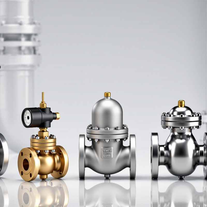
This guide compares five pressure relief valve options by performance, application, materials, certification, and service requirements. It examines spring-loaded, pilot-operated, pressure-vacuum, sanitary, and thermal relief designs. Each type solves a different problem. None is perfect.

Look closely at the nameplate. Check the set pressure, orifice size, inlet connection, outlet routing, and temperature rating. Ask whether the valve handles liquid, vapor, gas, or a changing mixture. Review the manufacturer’s test records and installation guidance. Independent engineering verification remains important, especially for critical systems.

The best choice is not always the most expensive valve. It is the valve that protects the equipment, fits the process, and can be tested safely. That sounds simple. It rarely is.
5 Best Pressure Relief Valves How to Choose?

Pressure Relief Valve Basics: Set Pressure, Blowdown, and MAWP

Choosing one of the five best pressure relief valves starts with three numbers: set pressure, blowdown, and MAWP. Set pressure is the pressure at which the valve begins to open under defined test conditions. It should protect the equipment without causing unnecessary lifting during normal operation. MAWP means maximum allowable working pressure. It is the highest pressure the protected vessel can safely withstand at its design temperature.

Keep the relationship clear. The valve set pressure should not exceed the equipment’s permitted limit, and the complete installation must follow the applicable engineering code. Temperature changes can alter material strength, so a pressure value alone is not enough.

Check the valve capacity against the actual gas or liquid flow. A valve that fits the pipe may still be badly sized.

Blowdown is the pressure drop required before the valve closes after relieving. Excessive blowdown can waste process fluid and delay reseating. Very small blowdown may cause chattering, especially with unstable pressure or poor inlet piping.

That detail is often overlooked. Inspectors should review backpressure, discharge routing, corrosion resistance, and maintenance access. A neat calculation is not proof of a reliable installation. Recheck assumptions when the service conditions change. Selecting a valve by pressure rating alone is a common, avoidable mistake.

Five Valve Types: Spring-Loaded, Pilot-Operated, Rupture Disc, and More

5 Best Pressure Relief Valves: How to Choose?

Spring-loaded valves are familiar, compact, and suitable for many clean fluids. They open when system pressure overcomes the spring force. Check the set pressure, temperature, discharge capacity, and backpressure before selecting one.

Pilot-operated valves provide tighter sealing and handle high-pressure systems efficiently. However, dirty fluids can block small pilot passages. Filtration and regular inspection matter.

Rupture discs respond instantly and contain no moving parts. They work well for rapid pressure spikes, corrosive service, or emergency protection. A disc must be replaced after bursting. It is not a resettable valve.

Buckling-pin devices offer predictable opening at a specified pressure and can resist vibration better than some discs. Their performance still depends on correct installation and temperature control.

No device is perfect.

Vacuum relief valves protect tanks from collapse during draining or cooling. They admit air or inert gas when internal pressure falls too low. For reliable selection, examine the fluid, flow rate, operating pressure, temperature changes, and discharge destination.

Field inspections often find problems at the outlet, not inside the valve. A blocked pipe, undersized vent, or poor mounting position can defeat good equipment. I would avoid choosing by pressure rating alone. That shortcut looks efficient, but it can create an unsafe mismatch. Have a qualified engineer verify the sizing and testing requirements for the complete system.

How to Size Capacity Using API 520 and ASME Section VIII

Choosing the five best pressure relief valves starts with the process, not the catalog. Spring-loaded, pilot-operated, balanced-bellows, thermal, and vacuum relief valves serve different hazards. I have seen sizing fail when engineers selected a valve before confirming fluid phase, fouling risk, or backpressure.

API 520 provides the sizing framework for pressure-relief devices. Calculate the required relieving rate from credible scenarios, such as blocked outlet, fire exposure, or utility failure. Then confirm set pressure, allowable overpressure, relieving temperature, molecular weight, compressibility, viscosity, and backpressure. Gas, liquid, steam, and two-phase flow require different equations and coefficients. Small errors matter.

ASME Section VIII defines vessel pressure limits and certification expectations. The valve set pressure must not exceed the vessel’s allowable working pressure. Use certified discharge coefficients and manufacturer capacity data for the selected valve design. For gas service, verify choked-flow assumptions. For liquid service, check viscosity and flashing. For built-up and superimposed backpressure, consider a balanced design or pilot-operated valve.

Keep the units consistent.

A practical review should compare calculated area with the next available orifice size, then verify inlet pressure loss and discharge piping reactions. I still recheck the calculation with an independent worksheet because unit conversions can quietly distort results. Field conditions may also differ from the original design basis. That uncertainty deserves documentation, not guesswork.

How to Choose Materials for Temperature, Pressure, and Corrosion

5 Best Pressure Relief Valves: How to Choose?

Choosing a pressure relief valve begins with the process conditions, not the valve catalog. Record the normal temperature, maximum pressure, fluid composition, and expected flow rate. A stainless steel body may suit clean water, but concentrated chemicals can attack it quickly. Carbon steel often handles high pressure economically, yet moisture and acidic vapors may cause pitting. Small details matter. Check the inlet and outlet connections carefully.

Temperature changes material strength. At high temperatures, seals can harden, soften, or lose elasticity. Metal seats usually tolerate heat better, but they may leak if particles damage the contact surface. For cryogenic service, select materials that remain tough below freezing. Do not assume a material works across the entire temperature range. Verify its pressure-temperature rating from reliable technical data.

Corrosion needs a practical review of the fluid and the environment. Chlorides, hydrogen sulfide, and wet steam create different risks. Consider the valve body, spring, seat, spindle, and fasteners separately. I once focused on the body material and overlooked the spring. That shortcut was wrong. The spring corroded first during a humid test. Material compatibility charts help, but real operating history and laboratory testing provide stronger evidence. Check pressure settings after installation, because vibration, heat cycling, and corrosion can gradually change performance.

How to Compare Five Valves by Standards, Testing, and Maintenance Needs

Choosing among five pressure relief valve designs requires more than comparing purchase prices. A conventional spring-loaded valve is simple and widely serviceable, but backpressure can shift its performance. A balanced bellows valve manages variable backpressure better, although its bellows needs careful inspection. A pilot-operated valve can handle high pressures and reduce simmering, yet dirty control lines may cause failure. Thermal relief valves protect blocked-in liquid systems from expansion. Vacuum relief valves serve low-pressure tanks and should not replace an overpressure device.

Standards provide a useful comparison point. Check the required local code, then review ASME Section VIII, API 520, API 527, or ISO 4126 requirements where applicable. These references address sizing, installation, performance, and seat leakage. Testing should confirm set pressure, blowdown, reseating, and leakage on a calibrated bench. A test tag alone proves little if the gauge was overdue for calibration. It is an uncomfortable detail, but field conditions often differ from workshop results.

Maintenance needs also separate the five choices. Inspect spring condition, bellows integrity, pilot filters, discharge piping, and tank connections. Record corrosion, vibration, deposits, and previous lifting events. Risk-based intervals are better than copying a generic calendar. Still, operating history can be incomplete. I would review the decision after every trip, leak, or process change. A valve that passed yesterday may not suit tomorrow’s pressure, temperature, or backpressure.

5 Best Pressure Relief Valves: How to Choose and Compare by Standards, Testing, and Maintenance Needs

Valve Type Best Application Operating Principle Typical Set-Pressure Range Back-Pressure Capability Relevant Standards and Tests Maintenance Demand Main Selection Consideration
Conventional Spring-Loaded Safety Valve General gas, steam, vapor, and liquid overpressure protection where outlet back pressure is low and stable. A spring applies closing force to a disc. Inlet pressure lifts the disc when it exceeds the calibrated set pressure. Commonly from approximately 1 to 250 bar, depending on design, size, and service. Limited. Built-up back pressure can change set pressure and reduce capacity unless the valve is specifically designed for it. ASME Section VIII; API 520 for sizing and selection; API 527 for seat tightness; API 576 for inspection and maintenance. Low to moderate. Inspect the spring, disc, seat, deposits, corrosion, and lifting mechanism at planned intervals. Choose it when the discharge system has minimal variable back pressure and a simple, economical design is preferred.
Balanced-Bellows Safety Valve Chemical, refining, and process services with variable or elevated superimposed back pressure. A bellows offsets the effect of back pressure on the spring and disc area, helping maintain more stable opening performance. Commonly from approximately 1 to 200 bar, depending on construction and temperature rating. Moderate to high, subject to bellows design, allowable pressure, temperature, and manufacturer calculations. ASME Section VIII; API 520; API 527; API 576; bellows integrity and pressure-boundary testing should be included in the inspection plan. Moderate. Bellows must be checked for cracking, corrosion, leakage, plugging of the vent, and loss of movement. Select it when back pressure may vary or when process emissions must be isolated from the spring chamber.
Pilot-Operated Pressure Relief Valve Large-flow gas systems, high-pressure vessels, pipelines, and applications requiring close operating margins. System pressure controls a pilot valve, which regulates pressure above the main piston or disc to open and close the main valve. Often from approximately 10 to 400 bar, depending on pilot and main-valve design. High potential capability, but performance depends on pilot configuration, sensing lines, discharge pressure, and flow conditions. ASME Section VIII; API 520; API 527 where applicable; API 576; functional testing of pilot, sensing line, filters, and control passages. Moderate to high. Small pilot orifices, filters, sensing lines, and moving parts require clean service and careful testing. Use it for high capacity, low accumulation, or operating pressures close to the set pressure, provided instrumentation and maintenance are reliable.
Liquid-Service Relief Valve Pumps, liquid-filled pipelines, heat exchangers, hydraulic systems, and blocked-in liquid sections. A spring-loaded or pilot-assisted mechanism opens to relieve liquid expansion or excessive hydraulic pressure. Commonly from approximately 2 to 150 bar, depending on the liquid service and valve construction. Usually limited to moderate values. Liquid discharge piping must be designed to prevent excessive pressure loss and hydraulic shock. API 520 for sizing principles; API 527 for seat tightness where applicable; API 576; applicable vessel, piping, and local pressure-equipment codes. Low to moderate. Check seat condition, corrosion, blocked discharge paths, trapped air, and compatibility with the process liquid. Select based on liquid density, viscosity, flashing potential, thermal expansion, required relieving capacity, and discharge-line pressure drop.
Thermal Relief Valve Small isolated liquid volumes exposed to heat, such as blocked-in piping, liquid lines, and jacketed equipment. Thermal expansion raises pressure in the trapped liquid. A compact spring-loaded valve opens at a preset pressure. Frequently set between approximately 3 and 40 bar, according to the protected system and code requirements. Generally low-flow service with limited back-pressure tolerance; discharge should be routed safely and without blockage. Applicable pressure-equipment codes; API 520 sizing principles where relevant; API 527 seat-tightness methods where applicable; documented set-pressure testing. Low. Verify the set pressure, seat condition, corrosion resistance, discharge path, and correct installation orientation. Choose it only for thermal expansion protection, not as a substitute for a full-capacity relief valve during fire or process overpressure scenarios.
Selection note: Final valve sizing and certification should be based on the protected equipment, relieving scenario, fluid properties, temperature, allowable accumulation, inlet pressure loss, outlet back pressure, and the governing local code. The pressure ranges shown are typical engineering ranges, not universal limits.