- Home
- A-Z Catalogue
- Products
- Valves
- Cetop
- Manual Directional Valves
- Proportional Valves
- Poppet Valves
- High-Speed Linear Servo Valves
- All High-Speed Linear Servo Valves
- Cetop 10 (NG32) Two Stage Type High Speed Linear Servo Valves – LSVHG-10
- Cetop 10 (NG32) Two Stage Type High Speed Linear Servo Valves – LSVHG-10 (With Fail-Safe)
- Cetop 8 (NG25) Two Stage Type High Speed Linear Servo Valves – LSVHG-06
- Cetop 8 (NG25) Two Stage Type High Speed Linear Servo Valves – LSVHG-06 (With Fail-Safe)
- Cetop 7 (NG16) Two Stage Type High Speed Linear Servo Valves – LSVHG-04
- Cetop 7 (NG16) Two Stage Type High Speed Linear Servo Valves – LSVHG-04 (With Fail-Safe)
- Cetop 5 (NG10) Direct Type High Speed Linear Servo Valves – LSVG-03
- Cetop 5 (NG10) OBE Type Direct Operated Linear Servo Valves – LSVG-03-EH
- Cetop 3 (NG6) OBE Type Direct Operated Linear Servo Valves – LSVG-01-EH
- Pumps
- Pressure control
- Flow Control Valves
- Pressure Control Valves
- All Pressure Control Valves
- Brake Valves
- Direct Relief Valve
- Low Noise Solenoid Controlled Relief Valves
- Low Noise Pilot Operated Relief Valves
- Pilot Operated Relief Valves
- Pressure reducing and relieving valves
- Pressure reducing and check valves
- Pressure control valves
- Remote Control Relief Valves
- Solenoid Controlled Relief Valves – BSG
- Solenoid Controlled Relief Valves – BST
- Unloading relief valves
- Check valves
- Environmental
- Valves
- Hydraulic Systems
- Power pack
- About Us
- Contact
- Blog

Why Is Die Casting Mold Design Important?
A Die Casting Mold may look like a steel block with polished cavities, but its design governs how molten metal fills, cools, and releases. A small mistake in gate placement can leave a thin section short of metal. Poor venting may trap air, while uneven cooling can distort a part or shorten tool life. These are not abstract risks; they show up on real production lines as scrap, rework, and downtime.
The market’s scale makes careful design matter. Grand View Research estimated the global die casting market at USD 73.5 billion in 2023 and projected a 6.4% compound annual growth rate from 2024 to 2030. Market growth alone does not prove that every project needs a complex mold. It does show why manufacturers scrutinize tooling decisions, from alloy selection to cooling-channel layout. The report measures market value, not mold performance, so those figures should be read in context.
Casting researcher and author John Campbell is a recognized authority on casting processes. A practical design maxim aligned with his work is: “A mold must control metal flow, heat, and solidification as one system.” That is a guiding principle, not a substitute for simulation or shop-floor testing. Real parts can still surprise you. A sound Die Casting Mold design connects product geometry with process conditions, inspection needs, and maintenance plans—and it leaves room to question assumptions before steel is cut.
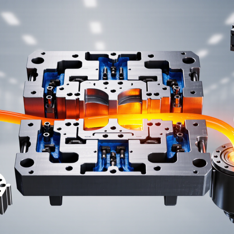
Table of Contents [Hide]
What Mold Design Controls in High-Pressure Die Casting at 70–100 MPa
Why Is Die Casting Mold Design Important?
What Mold Design Controls in High-Pressure Die Casting at 70–100 MPa
At 70–100 MPa, the machine drives molten metal into a closed steel die with substantial force. The exact pressure depends on the machine and process. Mold design helps control where the metal flows, how quickly the cavity fills, and where air escapes. A poorly placed gate can leave a cold seam or trap gas near a thin rib. Those defects may appear only after trimming or machining.
Vents and overflow wells give displaced air and early, cooler metal a path out. Cooling channels influence how evenly the die sheds heat, while the parting line and locking surfaces help resist separation and reduce flash. Small details matter. Even a slight change in wall thickness can alter filling and cooling, so trial results should guide adjustments rather than guesswork. Design cannot eliminate every defect, but it can make the process more predictable.
Tips: Review fill patterns, vent locations, and likely hot spots before cutting the die. Check sample parts for porosity, flash, and uneven dimensions. Keep a record of each adjustment; one improvement can expose another weak point. That is worth reviewing.