


- Home
- A-Z Catalogue
- Products
- Valves
- Cetop
- Manual Directional Valves
- Proportional Valves
- Poppet Valves
- High-Speed Linear Servo Valves
- All High-Speed Linear Servo Valves
- Cetop 10 (NG32) Two Stage Type High Speed Linear Servo Valves – LSVHG-10
- Cetop 10 (NG32) Two Stage Type High Speed Linear Servo Valves – LSVHG-10 (With Fail-Safe)
- Cetop 8 (NG25) Two Stage Type High Speed Linear Servo Valves – LSVHG-06
- Cetop 8 (NG25) Two Stage Type High Speed Linear Servo Valves – LSVHG-06 (With Fail-Safe)
- Cetop 7 (NG16) Two Stage Type High Speed Linear Servo Valves – LSVHG-04
- Cetop 7 (NG16) Two Stage Type High Speed Linear Servo Valves – LSVHG-04 (With Fail-Safe)
- Cetop 5 (NG10) Direct Type High Speed Linear Servo Valves – LSVG-03
- Cetop 5 (NG10) OBE Type Direct Operated Linear Servo Valves – LSVG-03-EH
- Cetop 3 (NG6) OBE Type Direct Operated Linear Servo Valves – LSVG-01-EH
- Pumps
- Pressure control
- Flow Control Valves
- Pressure Control Valves
- All Pressure Control Valves
- Brake Valves
- Direct Relief Valve
- Low Noise Solenoid Controlled Relief Valves
- Low Noise Pilot Operated Relief Valves
- Pilot Operated Relief Valves
- Pressure reducing and relieving valves
- Pressure reducing and check valves
- Pressure control valves
- Remote Control Relief Valves
- Solenoid Controlled Relief Valves – BSG
- Solenoid Controlled Relief Valves – BST
- Unloading relief valves
- Check valves
- Environmental
- Valves
- Hydraulic Systems
- Power pack
- About Us
- Contact
- Blog

What Are Bevel Gears and How Do They Work?
Bevel Gears are conical-toothed machine elements that transfer torque between intersecting shafts. Their teeth change rotational direction, often by 90 degrees. You can find them inside vehicle differentials, industrial reducers, robotics, and compact drive systems.
Gear specialist Dr. Hermann J. Stadtfeld has stated, “The gear is the heart of every gearbox.” This concise observation explains their importance. A bevel gear is not merely a wheel with angled teeth. Its pitch surface resembles a cone, while tooth geometry controls contact, noise, load capacity, and service life. Small design errors can create vibration. Heat can follow.
Imagine two shafts meeting like the hands of a mechanical elbow. One bevel gear drives the other across that angle. Straight bevel gears are simple and economical, but they can sound harsh at higher speeds. Spiral bevel gears engage more gradually, improving smoothness and load sharing. Hypoid gears offset the shafts and can deliver higher torque, although they demand careful lubrication and adjustment.
Reliable performance depends on more than selecting a gear type. Engineers consider module, pressure angle, ratio, speed, torque, material, tooth contact, and housing stiffness. Manufacturing accuracy matters. So does installation. Even a high-quality gear may fail when backlash or alignment is incorrect.
This guide examines what Bevel Gears are, how they work, and where their advantages become practical. It also acknowledges a common limitation: simplified diagrams can hide real contact patterns. Understanding that gap helps readers judge designs more realistically.
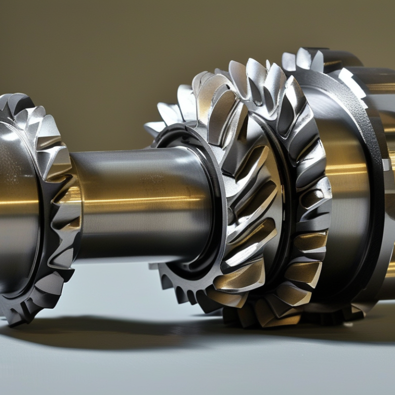
Table of Contents [Hide]
What Are Bevel Gears and What Makes Them Different?
Bevel gears are toothed wheels that transfer power between intersecting shafts. Their teeth form on a cone-shaped surface. This shape sets them apart from ordinary spur gears, whose teeth sit on cylindrical surfaces. A bevel gear can change rotation direction, commonly by 90 degrees. That angle matters. The gear pair also changes torque and speed according to their tooth counts.
In a working gearbox, the driving gear pushes the mating gear across angled tooth surfaces. Straight bevel gears have direct, sharp tooth engagement and suit moderate speeds. Spiral bevel gears use curved teeth that contact more gradually. They usually operate more quietly and carry higher loads. However, their curved teeth can create axial thrust. Designers must check shaft support, bearing capacity, lubrication, and tooth contact. A small installation error can produce uneven wear.
Bevel gears also differ from worm gears and helical gears because their main purpose involves changing shaft direction through conical geometry. Their performance depends on more than the gear ratio. Backlash, mounting distance, surface finish, and operating temperature all influence reliability. During a practical inspection, technicians may find polishing on one tooth side or small pits near the heel. These marks can indicate misalignment or excessive load. This is where simple explanations fail. Even a well-designed gear set can run poorly when assembly tolerances are ignored. In my view, maintenance records should include contact patterns, not only noise readings. Noise can appear after damage has already started.





