- Home
- A-Z Catalogue
- Products
- Valves
- Cetop
- Manual Directional Valves
- Proportional Valves
- Poppet Valves
- High-Speed Linear Servo Valves
- All High-Speed Linear Servo Valves
- Cetop 10 (NG32) Two Stage Type High Speed Linear Servo Valves – LSVHG-10
- Cetop 10 (NG32) Two Stage Type High Speed Linear Servo Valves – LSVHG-10 (With Fail-Safe)
- Cetop 8 (NG25) Two Stage Type High Speed Linear Servo Valves – LSVHG-06
- Cetop 8 (NG25) Two Stage Type High Speed Linear Servo Valves – LSVHG-06 (With Fail-Safe)
- Cetop 7 (NG16) Two Stage Type High Speed Linear Servo Valves – LSVHG-04
- Cetop 7 (NG16) Two Stage Type High Speed Linear Servo Valves – LSVHG-04 (With Fail-Safe)
- Cetop 5 (NG10) Direct Type High Speed Linear Servo Valves – LSVG-03
- Cetop 5 (NG10) OBE Type Direct Operated Linear Servo Valves – LSVG-03-EH
- Cetop 3 (NG6) OBE Type Direct Operated Linear Servo Valves – LSVG-01-EH
- Pumps
- Pressure control
- Flow Control Valves
- Pressure Control Valves
- All Pressure Control Valves
- Brake Valves
- Direct Relief Valve
- Low Noise Solenoid Controlled Relief Valves
- Low Noise Pilot Operated Relief Valves
- Pilot Operated Relief Valves
- Pressure reducing and relieving valves
- Pressure reducing and check valves
- Pressure control valves
- Remote Control Relief Valves
- Solenoid Controlled Relief Valves – BSG
- Solenoid Controlled Relief Valves – BST
- Unloading relief valves
- Check valves
- Environmental
- Valves
- Hydraulic Systems
- Power pack
- About Us
- Contact
- Blog

Top 10 Festo Pneumatic Connectors for Global Buyers
Selecting the right Festo Pneumatic Connectors can influence airflow stability, maintenance time, and production reliability. For global buyers, the choice involves more than matching a tube diameter. Material, thread standard, pressure range, temperature limits, and installation space must work together.
This guide reviews ten widely used options for different industrial applications. It considers push-in fittings for quick assembly, bulkhead connectors for compact panels, and threaded models for secure equipment interfaces. Practical experience shows that small details matter. A connector that fits perfectly on a test bench may become difficult to service inside a crowded machine.
Real conditions are different.
Each selection is assessed through manufacturer specifications, typical factory use, and installation considerations. Buyers should verify current product data, especially when ordering across regions with different thread conventions. Metric and imperial connections can look deceptively similar. That mistake may cause leakage, damaged threads, or unnecessary downtime.
The ranking is useful, but not absolute. A high-performing connector for packaging equipment may not suit a washdown line or a high-temperature process. We also recognize that availability, local support, and replacement lead times can change the final decision. Those factors are sometimes overlooked.
Reliable purchasing requires evidence, not assumptions. Compare operating pressure with the actual system requirement. Check tube compatibility before placing a large order. When possible, test one connector under vibration, repeated disconnection, and expected temperature changes. This approach helps global buyers balance performance, safety, serviceability, and long-term value.
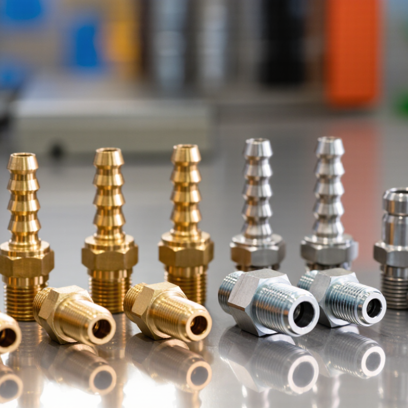
Table of Contents [Hide]
Festo Pneumatic Connectors: Types, Functions, and Selection Criteria
Pneumatic connectors join tubing, valves, actuators, and air preparation units while controlling airflow and preventing leakage. Common types include push-in, threaded, elbow, tee, reducer, and bulkhead connectors. Push-in models support rapid assembly, while threaded designs suit higher vibration and repeated servicing. Elbow connectors save space inside compact control cabinets.
Selection should begin with tube outside diameter, thread standard, working pressure, temperature range, and air quality. Check the connector material against moisture, oil, chemicals, and cleaning agents. A connector rated for 10 bar may still fail when temperature rises or tubing bends sharply.
That detail is easy to miss. ISO 4414 also emphasizes safe pneumatic system design, isolation, and controlled exhaust.
Automation growth makes these choices more important. The International Federation of Robotics reported 541,302 industrial robots installed worldwide in 2023. More robotic cells mean denser tubing layouts and greater demand for reliable connections.
Field inspections often find leakage near poorly cut tube ends, over-tightened threads, or unsupported bends. Flow capacity matters, too. A small internal passage can slow cylinder response, even when the external fitting looks adequate.
Buyers should compare pressure-drop data, installation space, replacement availability, and documented test results. Brand reputation helps, but it cannot replace dimensional checks. My own selection logic would still allow revision after real operating data arrives.