


- Home
- A-Z Catalogue
- Products
- Valves
- Cetop
- Manual Directional Valves
- Proportional Valves
- Poppet Valves
- High-Speed Linear Servo Valves
- All High-Speed Linear Servo Valves
- Cetop 10 (NG32) Two Stage Type High Speed Linear Servo Valves – LSVHG-10
- Cetop 10 (NG32) Two Stage Type High Speed Linear Servo Valves – LSVHG-10 (With Fail-Safe)
- Cetop 8 (NG25) Two Stage Type High Speed Linear Servo Valves – LSVHG-06
- Cetop 8 (NG25) Two Stage Type High Speed Linear Servo Valves – LSVHG-06 (With Fail-Safe)
- Cetop 7 (NG16) Two Stage Type High Speed Linear Servo Valves – LSVHG-04
- Cetop 7 (NG16) Two Stage Type High Speed Linear Servo Valves – LSVHG-04 (With Fail-Safe)
- Cetop 5 (NG10) Direct Type High Speed Linear Servo Valves – LSVG-03
- Cetop 5 (NG10) OBE Type Direct Operated Linear Servo Valves – LSVG-03-EH
- Cetop 3 (NG6) OBE Type Direct Operated Linear Servo Valves – LSVG-01-EH
- Pumps
- Pressure control
- Flow Control Valves
- Pressure Control Valves
- All Pressure Control Valves
- Brake Valves
- Direct Relief Valve
- Low Noise Solenoid Controlled Relief Valves
- Low Noise Pilot Operated Relief Valves
- Pilot Operated Relief Valves
- Pressure reducing and relieving valves
- Pressure reducing and check valves
- Pressure control valves
- Remote Control Relief Valves
- Solenoid Controlled Relief Valves – BSG
- Solenoid Controlled Relief Valves – BST
- Unloading relief valves
- Check valves
- Environmental
- Valves
- Hydraulic Systems
- Power pack
- About Us
- Contact
- Blog

10 Tips for Choosing a Solar Power System for RV
Choosing a Solar Power System For Rv is no longer a niche upgrade. It is a practical energy decision for campers seeking quieter nights, reliable refrigeration, and fewer campground hookups. The RV Industry Association reported approximately 11 million U.S. households owned an RV in 2021, creating a substantial market for mobile power solutions. Meanwhile, the International Energy Agency’s Renewables 2024 report identifies solar photovoltaic power as the world’s fastest-growing renewable technology.
Real-world selection requires more than counting rooftop panels. You must match daily watt-hours, battery chemistry, inverter capacity, roof space, shade exposure, and driving habits. A 200-watt array may support lights and device charging. It may struggle with an induction cooker, compressor refrigerator, or air conditioner. The details matter. Very much.
RV electrical specialist John Wiles has emphasized, “The battery is the heart of any stand-alone PV system.” That principle guides this article’s ten practical tips. We will examine energy audits, panel placement, lithium versus lead-acid batteries, charge controllers, wiring losses, installation safety, and seasonal performance. The U.S. Department of Energy’s Energy Saver resources also stress that system output depends on sunlight, orientation, and equipment efficiency.
One uncomfortable truth remains: advertised capacity rarely equals usable energy. I have seen buyers focus on panel wattage while overlooking battery reserve and cloudy-weather demands. That mistake is easy to repeat. Careful planning is less exciting, but more dependable. These recommendations aim to make your Solar Power System For Rv safer, more efficient, and better suited to the journeys you actually take.
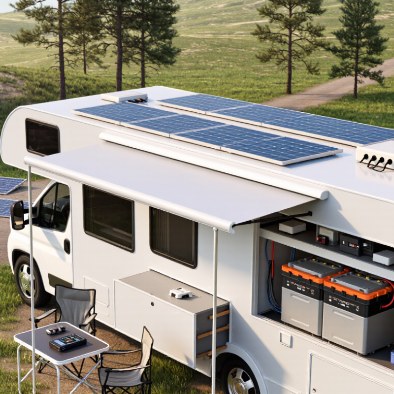
Table of Contents [Hide]
Assessing Your RV’s Energy Needs and Travel Habits
10 Tips for Choosing a Solar Power System for RV
Assessing Your RV’s Energy Needs and Travel Habits
Your travel routine matters more than a large panel count. The 2024 North American Camping Report recorded 57.8 million camping households in the United States during 2023. Many campers now combine remote stays with occasional campground hookups, creating very different power requirements. A weekend traveler may need lighting, phone charging, and a water pump. A remote worker may also run a laptop, router, refrigerator, and ventilation fan daily.
Write down each appliance, its wattage, and daily operating hours. For example, a 60-watt refrigerator running eight hours uses about 480 watt-hours. Add lighting, charging, heating controls, and inverter losses. The National Renewable Energy Laboratory’s PVWatts guidance shows that solar output changes with location, season, orientation, and shading. Tree cover at a campsite can reduce production sharply. It is easy to overestimate.
Keep a margin. My first estimate was too optimistic. A 1,000-watt-hour daily load may require roughly 1,300 watt-hours from the array after charging and conversion losses. Battery capacity should also reflect cloudy days, not only sunny afternoons. Check whether your trips include winter travel, long driving days, or several nights without hookups. The U.S. Energy Information Administration reports substantial seasonal variation in solar availability across regions, so one universal system size is unreliable. Measure real usage with a monitoring device for several trips, then adjust the system around evidence rather than guesswork.





