


- Home
- A-Z Catalogue
- Products
- Valves
- Cetop
- Manual Directional Valves
- Proportional Valves
- Poppet Valves
- High-Speed Linear Servo Valves
- All High-Speed Linear Servo Valves
- Cetop 10 (NG32) Two Stage Type High Speed Linear Servo Valves – LSVHG-10
- Cetop 10 (NG32) Two Stage Type High Speed Linear Servo Valves – LSVHG-10 (With Fail-Safe)
- Cetop 8 (NG25) Two Stage Type High Speed Linear Servo Valves – LSVHG-06
- Cetop 8 (NG25) Two Stage Type High Speed Linear Servo Valves – LSVHG-06 (With Fail-Safe)
- Cetop 7 (NG16) Two Stage Type High Speed Linear Servo Valves – LSVHG-04
- Cetop 7 (NG16) Two Stage Type High Speed Linear Servo Valves – LSVHG-04 (With Fail-Safe)
- Cetop 5 (NG10) Direct Type High Speed Linear Servo Valves – LSVG-03
- Cetop 5 (NG10) OBE Type Direct Operated Linear Servo Valves – LSVG-03-EH
- Cetop 3 (NG6) OBE Type Direct Operated Linear Servo Valves – LSVG-01-EH
- Pumps
- Pressure control
- Flow Control Valves
- Pressure Control Valves
- All Pressure Control Valves
- Brake Valves
- Direct Relief Valve
- Low Noise Solenoid Controlled Relief Valves
- Low Noise Pilot Operated Relief Valves
- Pilot Operated Relief Valves
- Pressure reducing and relieving valves
- Pressure reducing and check valves
- Pressure control valves
- Remote Control Relief Valves
- Solenoid Controlled Relief Valves – BSG
- Solenoid Controlled Relief Valves – BST
- Unloading relief valves
- Check valves
- Environmental
- Valves
- Hydraulic Systems
- Power pack
- About Us
- Contact
- Blog

What Is a Quick Connector and How Does It Work?
A Quick Connector looks simple, but its small body manages pressure, flow, alignment, and safety at once. You may find one between a hydraulic hose and a machine, behind a pneumatic panel, or inside irrigation equipment. Its purpose is practical: connect and disconnect fluid lines quickly, without repeatedly threading fittings or spilling large amounts of media.
Inside the connector, a plug meets a socket and pushes internal valves open. Springs, locking balls, and seals then hold the connection together. When disconnected, the valves close and limit leakage. The exact design depends on pressure, temperature, chemical compatibility, and the required flow rate. A connector for clean air may fail quickly in hot hydraulic oil. That detail is easy to overlook.
As fluid-power engineer Michael K. McDonald explains, “A connector is not merely a joining point; it is part of the system’s control and safety.” This view matters during selection. Thread size alone cannot determine performance. Material, seal type, coupling force, and contamination resistance matter too.
Not every connection is perfect.
A dusty workshop can damage a precision seal. A rushed installation can leave the plug partially locked. Even a high-quality Quick Connector may leak when used beyond its rated conditions. Therefore, understanding how it works is more valuable than choosing the cheapest option. This guide examines its internal mechanism, common designs, advantages, limitations, and practical inspection points. It also questions a common assumption: faster connection does not always mean better connection. Reliable performance comes from correct specification, careful handling, and regular maintenance.
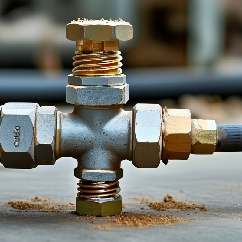
Table of Contents [Hide]
What Is a Quick Connector?
A quick connector is a fitting that joins pipes, hoses, or tubes without lengthy threading or special tools. It usually has a socket, locking sleeve, and internal seal. When the matching plug enters the socket, small balls or a locking ring hold it securely. The seal presses around the plug and helps prevent leaks. Disconnecting is simple. Pull back the sleeve, then remove the plug. The process saves time during equipment servicing. However, quick connectors are not foolproof. A damaged seal can leak suddenly under pressure.
Tips: Check the connector’s pressure and temperature ratings before installation. Clean both connection surfaces, even when they look nearly spotless. Push the plug fully into the socket until you feel or hear the lock engage. Gently pull it afterward. This small check can prevent an avoidable separation.
In practical maintenance, most problems come from poor alignment, worn seals, or trapped dirt. Never force a connector that resists insertion. Stop and inspect it. A light film of compatible lubricant may help some seals, but it can harm others. Follow the fitting manufacturer’s technical guidance. Replace cracked parts promptly. Test the connection at low pressure first, then increase pressure gradually. A quick connector should make work easier, not encourage careless installation.





