


- Home
- A-Z Catalogue
- Products
- Valves
- Cetop
- Manual Directional Valves
- Proportional Valves
- Poppet Valves
- High-Speed Linear Servo Valves
- All High-Speed Linear Servo Valves
- Cetop 10 (NG32) Two Stage Type High Speed Linear Servo Valves – LSVHG-10
- Cetop 10 (NG32) Two Stage Type High Speed Linear Servo Valves – LSVHG-10 (With Fail-Safe)
- Cetop 8 (NG25) Two Stage Type High Speed Linear Servo Valves – LSVHG-06
- Cetop 8 (NG25) Two Stage Type High Speed Linear Servo Valves – LSVHG-06 (With Fail-Safe)
- Cetop 7 (NG16) Two Stage Type High Speed Linear Servo Valves – LSVHG-04
- Cetop 7 (NG16) Two Stage Type High Speed Linear Servo Valves – LSVHG-04 (With Fail-Safe)
- Cetop 5 (NG10) Direct Type High Speed Linear Servo Valves – LSVG-03
- Cetop 5 (NG10) OBE Type Direct Operated Linear Servo Valves – LSVG-03-EH
- Cetop 3 (NG6) OBE Type Direct Operated Linear Servo Valves – LSVG-01-EH
- Pumps
- Pressure control
- Flow Control Valves
- Pressure Control Valves
- All Pressure Control Valves
- Brake Valves
- Direct Relief Valve
- Low Noise Solenoid Controlled Relief Valves
- Low Noise Pilot Operated Relief Valves
- Pilot Operated Relief Valves
- Pressure reducing and relieving valves
- Pressure reducing and check valves
- Pressure control valves
- Remote Control Relief Valves
- Solenoid Controlled Relief Valves – BSG
- Solenoid Controlled Relief Valves – BST
- Unloading relief valves
- Check valves
- Environmental
- Valves
- Hydraulic Systems
- Power pack
- About Us
- Contact
- Blog

What Is a Moved Chipper Machine and How Does It Work?
A Moved Chipper Machine is a mobile wood-processing unit designed to travel between logging sites, farms, parks, and urban tree-care projects. The term is not perfectly standardized. In many technical markets, it describes a mobile or towable wood chipper. That distinction matters because capacity, transport method, and safety controls vary widely.
The machine converts branches, trunks, and other woody residues into smaller chips. An operator places material into a feed hopper. Hydraulic rollers pull the wood toward rotating knives mounted on a disc or drum. The cutting chamber reduces the material rapidly. A discharge chute then throws the chips into a truck, trailer, or collection area. Some models use screens to control chip size. Others rely on knife design and rotor speed.
Scale changes everything.
According to the FAO Global Forest Resources Assessment 2020, forests cover about 31% of the world’s land area. That vast resource creates continuous demand for efficient residue handling. The U.S. Department of Energy’s 2023 Billion-Ton Report also identifies woody biomass as an important potential feedstock for bioenergy and bioproducts. These reports support the machine’s practical relevance, but they do not guarantee safe or profitable operation.
Real performance depends on moisture, wood diameter, knife sharpness, engine power, and feeding technique. A wet branch may leave uneven chips. A dull knife can increase vibration and fuel use. The U.S. Occupational Safety and Health Administration emphasizes guarding, lockout procedures, and controlled feeding around chipping equipment. This guide examines how a Moved Chipper Machine works, where it performs best, and which operating assumptions deserve closer review.
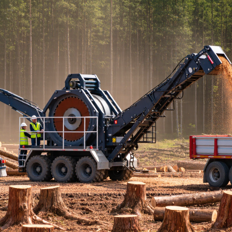
Table of Contents [Hide]
What Is a Moved Chipper Machine?
What Is a Moved Chipper Machine?
A moved chipper machine is a mobile wood-chipping unit designed to travel between work sites. The term is not perfectly standardized. In technical writing, “mobile wood chipper” is usually clearer. It may be mounted on wheels, a trailer, or a tracked frame. Operators use it near pruning areas, forests, farms, and construction sites. This reduces the need to carry bulky branches over long distances.
The machine pulls branches into a feed hopper. Rollers grip the material and guide it toward sharp knives or a cutting disc. The cutting system reduces limbs into chips, while a discharge chute directs them into a truck or storage pile. Hydraulic controls regulate feeding speed. A practical detail matters here: wet, twisted, or oversized wood can slow the process and increase vibration. The machine is powerful, but not careless-proof.
The U.S. Department of Energy’s 2016 Billion-Ton Report estimated that the country could supply nearly one billion dry tons of biomass annually by 2040. Mobile chippers can support this supply chain by processing residues closer to where they are produced. The FAO’s Global Forest Resources Assessment 2020 recorded about 4.06 billion hectares of forest worldwide, showing the scale of potential residue management. Still, output depends on species, moisture, knife condition, and operator experience. It is easy to overstate capacity. Field conditions often prove less predictable than laboratory figures.





