


- Home
- A-Z Catalogue
- Products
- Valves
- Cetop
- Manual Directional Valves
- Proportional Valves
- Poppet Valves
- High-Speed Linear Servo Valves
- All High-Speed Linear Servo Valves
- Cetop 10 (NG32) Two Stage Type High Speed Linear Servo Valves – LSVHG-10
- Cetop 10 (NG32) Two Stage Type High Speed Linear Servo Valves – LSVHG-10 (With Fail-Safe)
- Cetop 8 (NG25) Two Stage Type High Speed Linear Servo Valves – LSVHG-06
- Cetop 8 (NG25) Two Stage Type High Speed Linear Servo Valves – LSVHG-06 (With Fail-Safe)
- Cetop 7 (NG16) Two Stage Type High Speed Linear Servo Valves – LSVHG-04
- Cetop 7 (NG16) Two Stage Type High Speed Linear Servo Valves – LSVHG-04 (With Fail-Safe)
- Cetop 5 (NG10) Direct Type High Speed Linear Servo Valves – LSVG-03
- Cetop 5 (NG10) OBE Type Direct Operated Linear Servo Valves – LSVG-03-EH
- Cetop 3 (NG6) OBE Type Direct Operated Linear Servo Valves – LSVG-01-EH
- Pumps
- Pressure control
- Flow Control Valves
- Pressure Control Valves
- All Pressure Control Valves
- Brake Valves
- Direct Relief Valve
- Low Noise Solenoid Controlled Relief Valves
- Low Noise Pilot Operated Relief Valves
- Pilot Operated Relief Valves
- Pressure reducing and relieving valves
- Pressure reducing and check valves
- Pressure control valves
- Remote Control Relief Valves
- Solenoid Controlled Relief Valves – BSG
- Solenoid Controlled Relief Valves – BST
- Unloading relief valves
- Check valves
- Environmental
- Valves
- Hydraulic Systems
- Power pack
- About Us
- Contact
- Blog

What Are Metallized Film Capacitors?
What are Metallized Film Capacitors, and why do they remain important in modern electrical equipment? These components use a thin plastic film as insulation and a microscopic metal layer as an electrode. The film is commonly polypropylene or polyester, selected for different temperature, frequency, and size requirements. Manufacturers wind or stack these layers, then seal them inside a protective case. During a small dielectric breakdown, the metal around the fault can evaporate. This action isolates the damaged spot and helps preserve the capacitor’s operation. That detail matters.
In practical designs, engineers use Metallized Film Capacitors for filtering, snubber circuits, motor operation, power conversion, and energy coupling. Their low loss, stable capacitance, and strong pulse performance can support efficient equipment. However, performance depends on ripple current, ambient temperature, humidity, voltage, and switching frequency. A capacitor marked 450 VDC may not suit a circuit with sharp transients or continuous overload. Datasheets deserve careful reading. Look for dissipation factor, insulation resistance, life ratings, and recognized safety certifications. Relevant IEC requirements and manufacturer test data can strengthen a design decision. In production testing, technicians may inspect swelling, cracked cases, loose terminals, and abnormal heating.
The technology is reliable, but it is not indestructible. Self-healing can consume a small amount of electrode material after repeated faults. That trade-off is easy to overlook. Designers should also consider spacing, mounting stress, and cooling around the component. A well-chosen capacitor can quietly work for years; a poorly rated one may fail early. This guide examines construction, advantages, limitations, common types, and selection methods with practical engineering context. Some applications still need another capacitor technology. That is worth remembering.
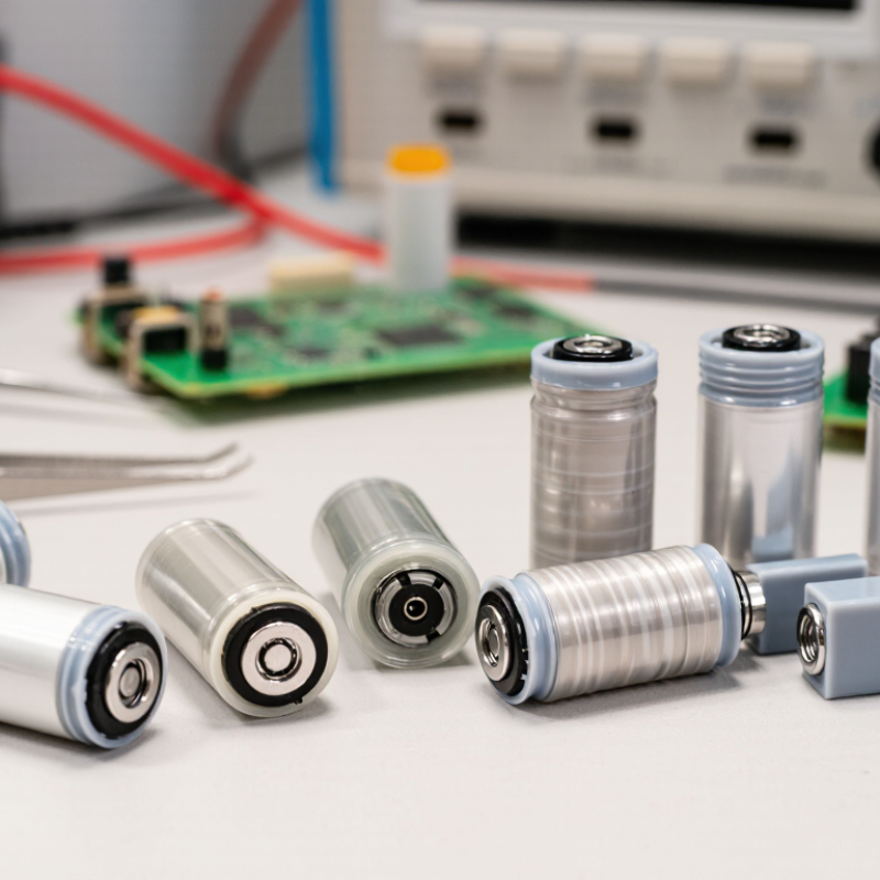
Table of Contents [Hide]
What Metallized Film Capacitors Are: Structure, Materials, and Core Functions
What Are Metallized Film Capacitors?
Metallized film capacitors use a thin plastic dielectric film with a vacuum-deposited metal layer. Polypropylene is common because it offers low dielectric loss and stable insulation. Polyester supports smaller designs but usually has higher losses. The metal layer is often aluminum or a zinc-based alloy. It is only a fraction of a micrometer thick, so the capacitor remains compact.
Manufacturers wind the coated film into a cylindrical roll or stack it into flat sections. Sprayed metal ends connect the internal layers to terminals. An outer case then protects the winding from humidity, vibration, and contamination. During a local dielectric breakdown, the metal around the fault can vaporize. This self-healing action usually preserves insulation, although it slowly reduces capacitance. It is useful, but not magic.
These capacitors store energy, suppress switching spikes, and filter ripple in power electronics. Metallized polypropylene types are widely used in DC-link, snubber, and AC-filter circuits. IEC 60384-16 defines requirements for fixed metallized polypropylene film capacitors for direct-current applications. A 2024 MarketsandMarkets report places the global film capacitor market on a growth path through 2029, driven partly by electrification and renewable-energy equipment. Market forecasts vary, however. Temperature, humidity, pulse current, and mounting stress can change actual service life. Engineers should check measured dissipation factor and thermal behavior, not only the printed capacitance. Real designs are less tidy than catalog tables.





