


- Home
- A-Z Catalogue
- Products
- Valves
- Cetop
- Manual Directional Valves
- Proportional Valves
- Poppet Valves
- High-Speed Linear Servo Valves
- All High-Speed Linear Servo Valves
- Cetop 10 (NG32) Two Stage Type High Speed Linear Servo Valves – LSVHG-10
- Cetop 10 (NG32) Two Stage Type High Speed Linear Servo Valves – LSVHG-10 (With Fail-Safe)
- Cetop 8 (NG25) Two Stage Type High Speed Linear Servo Valves – LSVHG-06
- Cetop 8 (NG25) Two Stage Type High Speed Linear Servo Valves – LSVHG-06 (With Fail-Safe)
- Cetop 7 (NG16) Two Stage Type High Speed Linear Servo Valves – LSVHG-04
- Cetop 7 (NG16) Two Stage Type High Speed Linear Servo Valves – LSVHG-04 (With Fail-Safe)
- Cetop 5 (NG10) Direct Type High Speed Linear Servo Valves – LSVG-03
- Cetop 5 (NG10) OBE Type Direct Operated Linear Servo Valves – LSVG-03-EH
- Cetop 3 (NG6) OBE Type Direct Operated Linear Servo Valves – LSVG-01-EH
- Pumps
- Pressure control
- Flow Control Valves
- Pressure Control Valves
- All Pressure Control Valves
- Brake Valves
- Direct Relief Valve
- Low Noise Solenoid Controlled Relief Valves
- Low Noise Pilot Operated Relief Valves
- Pilot Operated Relief Valves
- Pressure reducing and relieving valves
- Pressure reducing and check valves
- Pressure control valves
- Remote Control Relief Valves
- Solenoid Controlled Relief Valves – BSG
- Solenoid Controlled Relief Valves – BST
- Unloading relief valves
- Check valves
- Environmental
- Valves
- Hydraulic Systems
- Power pack
- About Us
- Contact
- Blog

How to Choose the Right Isolation Transformer?
Choosing the right Isolation Transformer is a practical engineering decision, not a simple catalog exercise. It affects electrical safety, equipment uptime, signal integrity, and maintenance costs. In hospitals, laboratories, factories, and data centers, a transformer must handle real operating conditions, including inrush current, nonlinear loads, heat, vibration, and limited installation space. Small errors matter.
The International Energy Agency reported that data centers consumed approximately 240–340 TWh of electricity globally in 2022. Its Electricity 2024 report projects demand could reach 620–1,050 TWh by 2026. This growth increases pressure on power quality and electrical resilience. An Isolation Transformer can help separate sensitive loads from upstream disturbances, but it cannot correct every voltage or grounding problem. The selection must consider voltage ratio, rated capacity, frequency, impedance, shielding, insulation class, and expected harmonic content. Noise matters. So does heat.
Safety and performance should be verified against recognized guidance, including IEC 61558, IEEE 1100, and applicable national electrical codes. Manufacturers should provide temperature-rise data, short-circuit withstand ratings, efficiency figures, acoustic levels, and routine test documentation. Independent certifications also improve confidence, although certification alone does not guarantee a suitable design. That assumption needs challenging. A technically compliant transformer may still fail under repeated motor starts or poorly balanced loads. This guide explains how to compare specifications, estimate actual demand, identify hidden installation risks, and select a dependable Isolation Transformer for the application rather than relying on price or nameplate capacity.
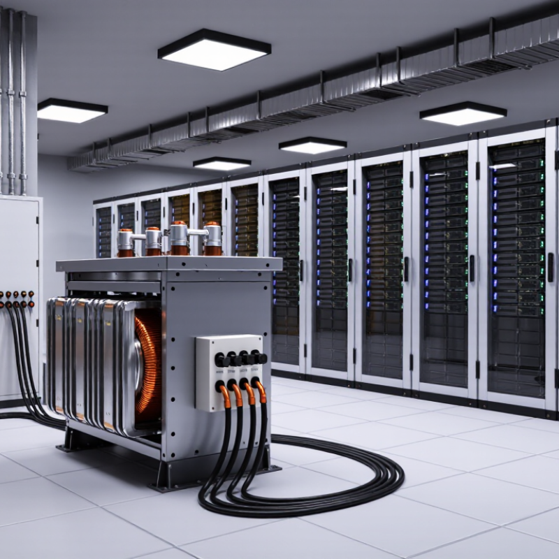
Table of Contents [Hide]
Understanding Isolation Transformers and Their Core Functions
How to Choose the Right Isolation Transformer?
Understanding Isolation Transformers and Their Core Functions
An isolation transformer separates the input circuit from the output circuit through magnetic coupling. Its windings share energy, but they do not share a direct electrical path. This separation is called galvanic isolation. It can reduce shock hazards, interrupt unwanted ground paths, and limit common-mode noise. The transformer does not automatically make every installation safe.
The transformer does not automatically make every installation safe.
Core function matters more than appearance. A one-to-one turns ratio usually maintains a similar voltage level. Other ratios can raise or reduce voltage. Check the required input voltage, output voltage, frequency, and load power before choosing one. Motors, switching supplies, and control systems may create high starting currents. A transformer sized only for normal running power can overheat or trip protection. That mistake is common.
Physical details deserve attention. Look for insulation ratings, dielectric test results, temperature limits, shielding, and suitable enclosure protection.
A shield between windings may reduce capacitive noise, but it needs correct grounding. In practical panel inspections, loose terminals and poor ventilation often cause more trouble than the transformer itself.
I would also verify the waveform, because some units perform poorly with distorted power. No choice is perfect. The application may change after installation, so measurements under real load remain valuable.





