- Home
- A-Z Catalogue
- Products
- Valves
- Cetop
- Manual Directional Valves
- Proportional Valves
- Poppet Valves
- High-Speed Linear Servo Valves
- All High-Speed Linear Servo Valves
- Cetop 10 (NG32) Two Stage Type High Speed Linear Servo Valves – LSVHG-10
- Cetop 10 (NG32) Two Stage Type High Speed Linear Servo Valves – LSVHG-10 (With Fail-Safe)
- Cetop 8 (NG25) Two Stage Type High Speed Linear Servo Valves – LSVHG-06
- Cetop 8 (NG25) Two Stage Type High Speed Linear Servo Valves – LSVHG-06 (With Fail-Safe)
- Cetop 7 (NG16) Two Stage Type High Speed Linear Servo Valves – LSVHG-04
- Cetop 7 (NG16) Two Stage Type High Speed Linear Servo Valves – LSVHG-04 (With Fail-Safe)
- Cetop 5 (NG10) Direct Type High Speed Linear Servo Valves – LSVG-03
- Cetop 5 (NG10) OBE Type Direct Operated Linear Servo Valves – LSVG-03-EH
- Cetop 3 (NG6) OBE Type Direct Operated Linear Servo Valves – LSVG-01-EH
- Pumps
- Pressure control
- Flow Control Valves
- Pressure Control Valves
- All Pressure Control Valves
- Brake Valves
- Direct Relief Valve
- Low Noise Solenoid Controlled Relief Valves
- Low Noise Pilot Operated Relief Valves
- Pilot Operated Relief Valves
- Pressure reducing and relieving valves
- Pressure reducing and check valves
- Pressure control valves
- Remote Control Relief Valves
- Solenoid Controlled Relief Valves – BSG
- Solenoid Controlled Relief Valves – BST
- Unloading relief valves
- Check valves
- Environmental
- Valves
- Hydraulic Systems
- Power pack
- About Us
- Contact
- Blog

How to Choose the Best SBMA Connector in 2026
Choosing the right Sbma Connector in 2026 takes more than comparing prices or connector dimensions. A small mismatch can affect signal performance, installation time, and long-term reliability. Start with the equipment it must connect to, then verify the mating interface against the manufacturer’s drawings. Names can be confusing. Do not rely on a product title alone.
Frequency range and impedance deserve careful attention, especially in compact RF assemblies. Check the datasheet for supported operating conditions, insertion loss, and return loss where those values matter to your design. Then consider the real installation: available clearance, cable type, expected mating cycles, and exposure to vibration, moisture, or temperature changes. A connector that fits on a bench may be awkward inside a crowded enclosure. Details matter.
This guide explains how to compare those requirements and assess build quality without treating marketing claims as test results. Look for traceable specifications, clear dimensional drawings, and consistent quality documentation. When possible, confirm critical measurements with a qualified supplier or test setup before committing to a large order. I would not choose from a headline specification alone; it can omit the limitation that matters most. No single option suits every application. The best choice balances verified electrical performance, mechanical fit, durability, and cost for the intended system.
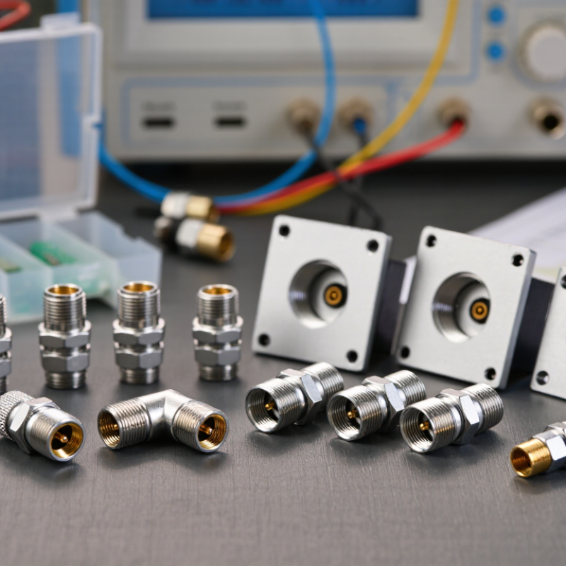
Table of Contents [Hide]
Define the SBMA Connector: 50 Ω Blind-Mate RF Interface
An SBMA connector is a 50 Ω radio-frequency interface designed for blind mating. Two assemblies connect as they slide into position, often inside a chassis. The contact faces may not be visible during installation. No cable wrenching. The 50 Ω value describes the intended impedance; it does not guarantee that the complete signal path will perform well.
Choosing one means checking more than the mating interface. Confirm the operating frequency, allowable insertion loss, return loss, and power needs for your system. Then check the mechanical details: mounting depth, alignment range, and how much movement the connector can tolerate. A small offset between modules can affect contact and RF performance. Measure the actual stack-up, not just the drawing.
Look closely at how the connector will be installed and serviced. Repeated mating, vibration, and dust near the interface can change performance over time. Ask for test data across the frequency range you plan to use, and verify it in a representative assembly. A datasheet alone may leave gaps. I would also inspect a sample after several mating cycles; it is an easy step to overlook when schedules get tight.