- Home
- A-Z Catalogue
- Products
- Valves
- Cetop
- Manual Directional Valves
- Proportional Valves
- Poppet Valves
- High-Speed Linear Servo Valves
- All High-Speed Linear Servo Valves
- Cetop 10 (NG32) Two Stage Type High Speed Linear Servo Valves – LSVHG-10
- Cetop 10 (NG32) Two Stage Type High Speed Linear Servo Valves – LSVHG-10 (With Fail-Safe)
- Cetop 8 (NG25) Two Stage Type High Speed Linear Servo Valves – LSVHG-06
- Cetop 8 (NG25) Two Stage Type High Speed Linear Servo Valves – LSVHG-06 (With Fail-Safe)
- Cetop 7 (NG16) Two Stage Type High Speed Linear Servo Valves – LSVHG-04
- Cetop 7 (NG16) Two Stage Type High Speed Linear Servo Valves – LSVHG-04 (With Fail-Safe)
- Cetop 5 (NG10) Direct Type High Speed Linear Servo Valves – LSVG-03
- Cetop 5 (NG10) OBE Type Direct Operated Linear Servo Valves – LSVG-03-EH
- Cetop 3 (NG6) OBE Type Direct Operated Linear Servo Valves – LSVG-01-EH
- Pumps
- Pressure control
- Flow Control Valves
- Pressure Control Valves
- All Pressure Control Valves
- Brake Valves
- Direct Relief Valve
- Low Noise Solenoid Controlled Relief Valves
- Low Noise Pilot Operated Relief Valves
- Pilot Operated Relief Valves
- Pressure reducing and relieving valves
- Pressure reducing and check valves
- Pressure control valves
- Remote Control Relief Valves
- Solenoid Controlled Relief Valves – BSG
- Solenoid Controlled Relief Valves – BST
- Unloading relief valves
- Check valves
- Environmental
- Valves
- Hydraulic Systems
- Power pack
- About Us
- Contact
- Blog

How to Choose an Industrial Power Supply
Choosing an Industrial Power Supply is not just a matter of matching the output voltage on a label. A unit rated for 24 V may still fail to support a system’s actual load, startup surge, or operating environment. Check the required voltage and current, then allow sensible headroom for continuous operation. A small control cabinet on a factory floor faces different demands from a clean, temperature-controlled test bench.
Look closely at the details. Motors, relays, and other inductive loads can draw brief startup currents that ordinary steady-state calculations miss. Heat matters, too: a supply rated at full output in cool conditions may need derating inside a warm, crowded enclosure. Consider efficiency, ripple, mounting space, cooling, and protection against overloads or short circuits. Verify that the specifications and approvals suit the equipment and installation where the unit will be used.
Measure twice.
A neat spreadsheet can still miss a real-world detail, such as a long cable run or a cabinet fan that has stopped working. That is worth admitting before choosing a model. Compare manufacturer datasheets, check the load profile, and confirm performance under expected temperature and input-voltage conditions. If a specification is unclear, ask the manufacturer rather than relying on a product title or sales summary. The right choice balances electrical performance, physical fit, reliability, and service needs. This guide explains how to assess those factors and select a supply that fits the application—not merely one that looks adequate on paper.
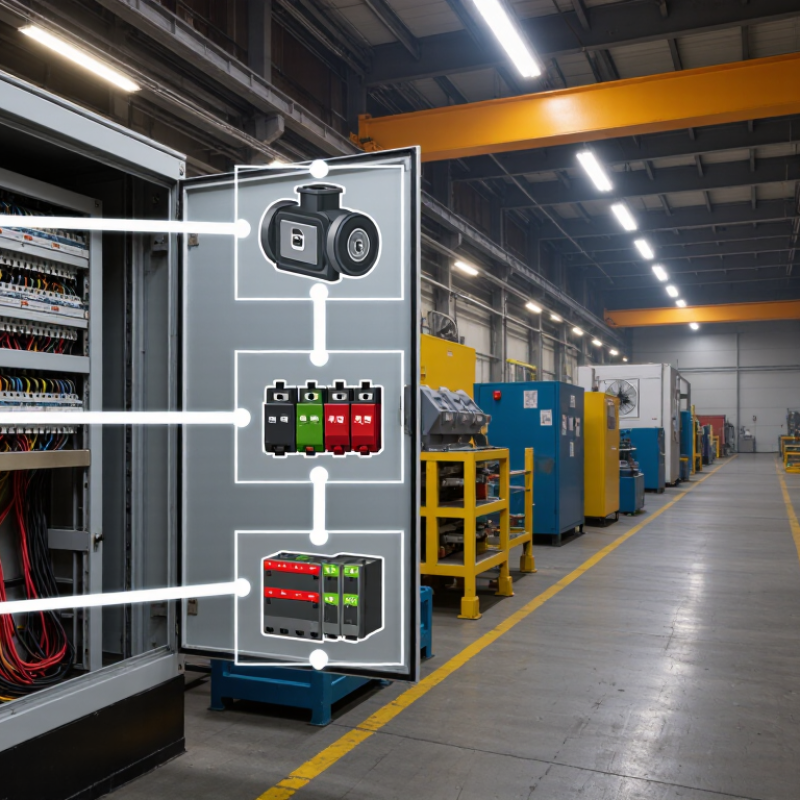
Table of Contents [Hide]
Identify the Load and Operating Requirements
Identify every load before choosing an industrial power supply. Record each device’s voltage, steady-state current, and startup demand. Note which loads switch on together. A PLC drawing 0.4 A is different from a relay bank that briefly pulls several times its normal current. Include temperature, enclosure ventilation, and expected operating hours; heat can reduce a supply’s usable output. Nameplate totals alone can mislead.
The U.S. Department of Energy’s Improving Motor and Drive System Performance sourcebook reports that motor-driven systems account for about 69% of electricity use in U.S. manufacturing. That figure is a reminder to separate motor loads from sensitive control loads. A motor’s startup surge may disturb a shared control rail, even when average demand looks acceptable. Check the equipment manuals for peak-current duration, then compare the combined demand against the supply’s derating curve. Add headroom where measurements or future expansion justify it, rather than applying an arbitrary margin. A spreadsheet can still miss a short surge.
Tips: Measure voltage at the load during startup, not only at the supply terminals. Record the worst case. Recheck the estimate after commissioning.
How to Choose an Industrial Power Supply - Identify the Load and Operating Requirements
| Load or application | Typical load requirements | Key operating considerations | Selection guidance |
|---|---|---|---|
| PLC and control circuitry | 24 V DC; example load: 1.5 A (36 W) | Requires a stable DC output; account for connected I/O modules and any expansion. | Allow capacity for the full measured load plus a practical reserve, commonly around 20–25% when conditions permit. |
| Industrial sensors | Often 24 V DC; example group load: 0.8 A (19.2 W) | Add the current draw of every sensor, transmitter, and interface device; check the specified voltage range. | Confirm the supply maintains adequate voltage at the load, including voltage drop in long cable runs. |
| Relay and contactor coils | Commonly 24 V DC; current varies by coil and operating state | Several coils may energize simultaneously; inductive loads can generate voltage transients when switched. | Size for the maximum simultaneous pickup current and use suitable suppression where required by the load or control design. |
| Solenoid valve | Example: 24 V DC, 0.5 A while energized (12 W) | Check whether the coil is continuous-duty or intermittent-duty and whether multiple valves can switch together. | Use the coil’s specified current and duty rating; include simultaneous operation and switching effects in the calculation. |
| DC motor or actuator | Varies by motor; running current may be substantially lower than startup or stall current. | Starting, acceleration, reversal, and stall conditions can cause brief high-current demand. | Check motor and drive specifications for peak current and duration; verify the supply’s overload behavior and transient response. |
| Industrial communication equipment | Often 24 V DC; example device load: 0.4 A (9.6 W) | Include all switches, gateways, and accessories; consider the effect of a power interruption on communications. | Check total continuous demand and, where continuity is essential, assess a suitable backup or redundancy arrangement. |
| Control cabinet operating conditions | Input supply, ambient temperature, installation method, and required output voltage depend on the site. | High temperature, restricted airflow, altitude, dust, vibration, and cabinet layout can affect permitted operation. | Check the supply’s derating curves, input-voltage range, mounting clearances, and applicable environmental ratings for the actual installation. |
Example load values are illustrative, not equipment specifications. Confirm each device’s rated voltage, continuous current, peak or inrush demand, duty cycle, and environmental limits before sizing the power supply.