


- Home
- A-Z Catalogue
- Products
- Valves
- Cetop
- Manual Directional Valves
- Proportional Valves
- Poppet Valves
- High-Speed Linear Servo Valves
- All High-Speed Linear Servo Valves
- Cetop 10 (NG32) Two Stage Type High Speed Linear Servo Valves – LSVHG-10
- Cetop 10 (NG32) Two Stage Type High Speed Linear Servo Valves – LSVHG-10 (With Fail-Safe)
- Cetop 8 (NG25) Two Stage Type High Speed Linear Servo Valves – LSVHG-06
- Cetop 8 (NG25) Two Stage Type High Speed Linear Servo Valves – LSVHG-06 (With Fail-Safe)
- Cetop 7 (NG16) Two Stage Type High Speed Linear Servo Valves – LSVHG-04
- Cetop 7 (NG16) Two Stage Type High Speed Linear Servo Valves – LSVHG-04 (With Fail-Safe)
- Cetop 5 (NG10) Direct Type High Speed Linear Servo Valves – LSVG-03
- Cetop 5 (NG10) OBE Type Direct Operated Linear Servo Valves – LSVG-03-EH
- Cetop 3 (NG6) OBE Type Direct Operated Linear Servo Valves – LSVG-01-EH
- Pumps
- Pressure control
- Flow Control Valves
- Pressure Control Valves
- All Pressure Control Valves
- Brake Valves
- Direct Relief Valve
- Low Noise Solenoid Controlled Relief Valves
- Low Noise Pilot Operated Relief Valves
- Pilot Operated Relief Valves
- Pressure reducing and relieving valves
- Pressure reducing and check valves
- Pressure control valves
- Remote Control Relief Valves
- Solenoid Controlled Relief Valves – BSG
- Solenoid Controlled Relief Valves – BST
- Unloading relief valves
- Check valves
- Environmental
- Valves
- Hydraulic Systems
- Power pack
- About Us
- Contact
- Blog

How to Choose an Air Conditioner Contactor in 2026?
Choosing the right Air Conditioner Contactor in 2026 requires more than matching voltage and horsepower. This small switching device controls compressor and fan motors, often under demanding starting conditions. A poor choice can cause buzzing, welded contacts, nuisance trips, or premature compressor damage. The correct selection begins with the equipment nameplate, wiring diagram, and manufacturer specifications. Check the motor’s rated load current, locked-rotor current, coil voltage, contact configuration, and operating frequency. Never rely on appearance alone.
Field experience shows that installation details matter as much as catalog ratings. A contactor exposed to heat, dust, moisture, or frequent cycling needs suitable durability and enclosure protection. Verify the pole arrangement, terminal capacity, mounting pattern, and compatibility with the existing control circuit. For modern systems, consider diagnostics and dependable coil performance, but avoid paying for features the unit cannot use. Standards and certification markings also deserve careful review. They provide useful evidence, not an automatic guarantee.
Small details matter.
A familiar brand can still be the wrong fit. A lower-priced model may look attractive, yet weak contacts can create costly downtime. Conversely, an oversized contactor may not solve a control-voltage mismatch. This guide examines practical selection criteria, common mistakes, and verification steps for residential and light commercial equipment. It also recognizes an uncomfortable truth: documentation is sometimes incomplete, and field conditions may differ from the design assumptions. When uncertainty remains, confirm the specifications with a qualified HVAC professional and follow the equipment manufacturer’s instructions. Reliable selection is not guesswork; it is a careful comparison of electrical data, operating conditions, and long-term service needs.
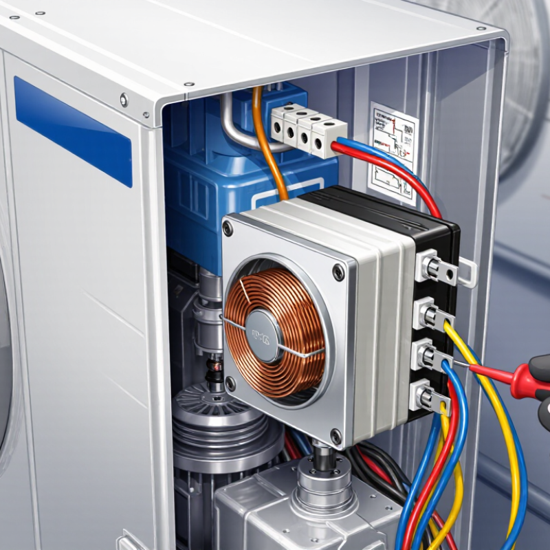
Table of Contents [Hide]
Understand the Role and Types of Air Conditioner Contactors
How to Choose an Air Conditioner Contactor in 2026?
An air conditioner contactor is an electrically controlled switch. It connects the compressor, condenser fan, or electric heater to the power supply. The control board sends a low-voltage signal, while the contactor handles higher current. It must interrupt motor loads safely. A loose, undersized contactor may cause buzzing, overheating, or burned terminals.
Types matter. Electromagnetic contactors remain common in split systems and packaged units. Solid-state contactors switch quietly and reduce mechanical wear, but they need suitable heat dissipation. Select the correct pole count for the circuit. Check coil voltage, full-load current, locked-rotor current, horsepower rating, utilization category, and short-circuit rating. AC-1 ratings suit mostly resistive loads; compressor motors usually require a motor-duty rating, such as AC-3. Never choose by physical size alone.
The U.S. Department of Energy reports that heating and cooling use about 48% of energy in a typical American home. The International Energy Agency’s 2018 cooling report projects global cooling demand could more than triple by 2050. That makes dependable switching increasingly important. In field work, I also inspect terminal torque, enclosure temperature, and auxiliary contacts. Small details matter. Yet one assumption deserves review: a higher current rating is not automatically better. Excess capacity can increase cost, while the wrong coil voltage can stop the system completely. Verify the nameplate and the installation conditions before replacing anything.





