- Home
- A-Z Catalogue
- Products
- Valves
- Cetop
- Manual Directional Valves
- Proportional Valves
- Poppet Valves
- High-Speed Linear Servo Valves
- All High-Speed Linear Servo Valves
- Cetop 10 (NG32) Two Stage Type High Speed Linear Servo Valves – LSVHG-10
- Cetop 10 (NG32) Two Stage Type High Speed Linear Servo Valves – LSVHG-10 (With Fail-Safe)
- Cetop 8 (NG25) Two Stage Type High Speed Linear Servo Valves – LSVHG-06
- Cetop 8 (NG25) Two Stage Type High Speed Linear Servo Valves – LSVHG-06 (With Fail-Safe)
- Cetop 7 (NG16) Two Stage Type High Speed Linear Servo Valves – LSVHG-04
- Cetop 7 (NG16) Two Stage Type High Speed Linear Servo Valves – LSVHG-04 (With Fail-Safe)
- Cetop 5 (NG10) Direct Type High Speed Linear Servo Valves – LSVG-03
- Cetop 5 (NG10) OBE Type Direct Operated Linear Servo Valves – LSVG-03-EH
- Cetop 3 (NG6) OBE Type Direct Operated Linear Servo Valves – LSVG-01-EH
- Pumps
- Pressure control
- Flow Control Valves
- Pressure Control Valves
- All Pressure Control Valves
- Brake Valves
- Direct Relief Valve
- Low Noise Solenoid Controlled Relief Valves
- Low Noise Pilot Operated Relief Valves
- Pilot Operated Relief Valves
- Pressure reducing and relieving valves
- Pressure reducing and check valves
- Pressure control valves
- Remote Control Relief Valves
- Solenoid Controlled Relief Valves – BSG
- Solenoid Controlled Relief Valves – BST
- Unloading relief valves
- Check valves
- Environmental
- Valves
- Hydraulic Systems
- Power pack
- About Us
- Contact
- Blog

What Is a Crawler Drive Motor and How Does It Work?
A Crawler Drive Motor turns hydraulic pressure into the steady track movement that lets excavators and other tracked machines climb, pivot, and work on uneven ground. It sits within the travel-drive assembly, where hydraulic flow powers a motor and reduction gears deliver usable torque to the track sprocket. Simple in principle. Demanding in practice.
Industry context helps explain why this component matters. The Association of Equipment Manufacturers (AEM) publishes construction equipment market reports that track sales and demand trends, while Off-Highway Research analyzes global construction equipment markets. These reports describe a large, active equipment sector, but they do not measure crawler motor reliability directly. That distinction matters. A market forecast cannot tell an owner how long a motor will last on a muddy, heavily loaded jobsite.
This guide explains what a Crawler Drive Motor does, how its main parts work together, and what affects travel performance. We’ll follow the path from hydraulic oil entering the motor to torque reaching the tracks. We’ll also look at warning signs such as slow travel, unequal turning, leaks, or unusual heat. These symptoms can point to motor wear, but they may also come from restricted hoses, contaminated oil, or a failing final drive. Diagnosis takes care. A rushed replacement can miss the real cause. Maintenance records, pressure checks, and the machine’s service manual provide stronger evidence than guesswork alone.
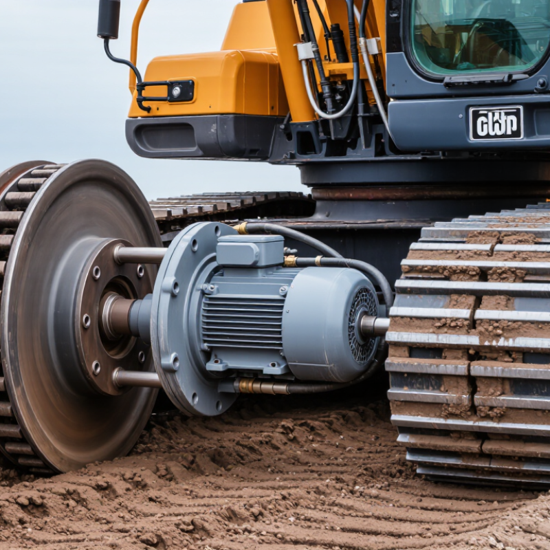
Table of Contents [Hide]
What a Crawler Drive Motor Is: Hydraulic Motor and Final Drive
A crawler drive motor is a hydraulic motor paired with a final drive, which reduces speed and multiplies torque at the track. Pressurized oil enters the motor and acts on internal pistons or gears, creating rotation. The final drive’s planetary gears then deliver that rotation to the sprocket. The result is controlled track movement, even when the machine pushes against soil or climbs a slope. Small detail, big effect. A leaking seal or restricted oil flow can reduce tractive effort and raise operating temperatures.
The motor and final drive must be matched to the machine’s weight, travel speed, and working conditions. The reduction gears handle substantial loads, while clean oil helps protect their close-fitting surfaces. ISO 4406:2021 classifies hydraulic-fluid cleanliness using particle counts at 4, 6, and 14 micrometres, a useful reference when checking filtration and fluid condition. On a muddy jobsite, inspection may reveal damage that a dashboard cannot. Still, cleanliness codes do not diagnose every fault; pressure, leakage, and temperature checks matter too. One point deserves reflection: a sluggish track does not automatically mean the motor has failed. The problem may sit in the final drive, the hydraulic circuit, or a service issue elsewhere.
| System Element | Input | What It Does | Output or Practical Detail |
|---|---|---|---|
| Main Components and Their Roles | |||
| Hydraulic pump | Mechanical power from the engine or electric motor | Moves pressurized hydraulic fluid through the travel circuit. | Supplies fluid flow; flow rate influences hydraulic motor speed. |
| Travel control valve | Pressurized hydraulic fluid and operator or controller commands | Directs fluid to the selected travel motor and can control direction and flow. | Controls forward or reverse travel and helps regulate track speed. |
| Hydraulic drive motor | Hydraulic fluid flow and pressure | Converts hydraulic power into rotary mechanical power. | Motor speed is primarily related to fluid flow; available torque is primarily related to pressure difference. |
| Final drive (travel gearbox) | Rotary output from the hydraulic motor | Uses reduction gearing to lower output speed and increase torque at the sprocket. | Often incorporates planetary gears; the exact gearing and layout vary by machine. |
| Drive sprocket and track | Reduced, higher-torque rotary output | The sprocket engages the track links and propels the crawler machine. | Track speed depends on drive rotation, sprocket size, and the selected travel setting. |
| Case drain and return circuit | Internal leakage flow and returning hydraulic fluid | Carries leakage or return oil back toward the hydraulic system while helping manage heat and pressure. | Routing and allowable back pressure must follow the machine and component specifications. |
| How the Drive Works | |||
| 1. Power generation | Engine or electric motor power | Drives the hydraulic pump. | Mechanical power becomes hydraulic power in the form of fluid flow and pressure. |
| 2. Travel command | Operator input, such as a travel lever or pedal | The control system meters and directs oil to one or both travel motors. | Changing flow direction reverses motor rotation; changing flow can change travel speed. |
| 3. Torque conversion | Pressure difference across the hydraulic motor | The motor produces rotating torque. | Greater pressure difference generally allows greater motor torque, subject to component limits and operating conditions. |
| 4. Speed reduction | High-speed, lower-torque motor rotation | The final drive reduces rotational speed through its gear train. | Reduction increases torque available at the drive sprocket, with some power lost to mechanical and hydraulic inefficiencies. |
| 5. Machine movement | Sprocket rotation | The sprocket pulls the track around the undercarriage. | Independent left and right travel drives enable steering by producing different track speeds or directions. |
| Operating Factors and Service Checks | |||
| Hydraulic fluid flow | Volume per unit of time | Primarily affects hydraulic motor rotational speed. | Insufficient flow can reduce travel speed; actual results depend on the motor and control system. |
| Hydraulic pressure | Force per unit area in the circuit | Provides the pressure difference needed to produce motor torque. | Use the machine’s specified pressure limits; excessive pressure can damage system components. |
| Final-drive lubrication | Specified gear oil at the correct level | Lubricates gears and bearings and helps carry away heat. | Check for leaks, contamination, abnormal noise, and metal particles according to the service schedule. |
| Heat and leakage | Operating load, fluid condition, and component wear | Excessive heat or leakage can indicate restricted flow, overloading, or wear. | Diagnose using the machine service procedure rather than relying on temperature or sound alone. |