- Home
- A-Z Catalogue
- Products
- Valves
- Cetop
- Manual Directional Valves
- Proportional Valves
- Poppet Valves
- High-Speed Linear Servo Valves
- All High-Speed Linear Servo Valves
- Cetop 10 (NG32) Two Stage Type High Speed Linear Servo Valves – LSVHG-10
- Cetop 10 (NG32) Two Stage Type High Speed Linear Servo Valves – LSVHG-10 (With Fail-Safe)
- Cetop 8 (NG25) Two Stage Type High Speed Linear Servo Valves – LSVHG-06
- Cetop 8 (NG25) Two Stage Type High Speed Linear Servo Valves – LSVHG-06 (With Fail-Safe)
- Cetop 7 (NG16) Two Stage Type High Speed Linear Servo Valves – LSVHG-04
- Cetop 7 (NG16) Two Stage Type High Speed Linear Servo Valves – LSVHG-04 (With Fail-Safe)
- Cetop 5 (NG10) Direct Type High Speed Linear Servo Valves – LSVG-03
- Cetop 5 (NG10) OBE Type Direct Operated Linear Servo Valves – LSVG-03-EH
- Cetop 3 (NG6) OBE Type Direct Operated Linear Servo Valves – LSVG-01-EH
- Pumps
- Pressure control
- Flow Control Valves
- Pressure Control Valves
- All Pressure Control Valves
- Brake Valves
- Direct Relief Valve
- Low Noise Solenoid Controlled Relief Valves
- Low Noise Pilot Operated Relief Valves
- Pilot Operated Relief Valves
- Pressure reducing and relieving valves
- Pressure reducing and check valves
- Pressure control valves
- Remote Control Relief Valves
- Solenoid Controlled Relief Valves – BSG
- Solenoid Controlled Relief Valves – BST
- Unloading relief valves
- Check valves
- Environmental
- Valves
- Hydraulic Systems
- Power pack
- About Us
- Contact
- Blog

Why Choose the Right Mount Motor for Your Application?
Choosing the right Mount Motor begins with understanding the machine it must serve. A motor that performs well on a workbench may struggle when mounted inside a vibrating enclosure or exposed to frequent starts. Load, speed, duty cycle, available space, and operating temperature all shape the decision. Ignore one, and the result can be excess heat, noise, or premature wear. Small details matter.
This guide explains how to compare motor types, mounting arrangements, torque requirements, and control options in practical terms. It also considers installation conditions, maintenance access, and the information worth checking in a manufacturer’s datasheet. A few minutes spent measuring a shaft, checking clearance, or recording the real load can prevent a costly mismatch. These checks are useful, but they cannot replace testing under actual operating conditions.
There is no universally best Mount Motor. The right choice depends on the application and its limits. A compact unit may save space yet leave little room for cooling. A more powerful motor may seem safer, though it can add cost and consume more energy than needed. That trade-off deserves a closer look. The recommendations that follow offer a grounded starting point, not a promise of perfect performance. Even careful selection can miss something; real equipment has a way of revealing the detail nobody measured.
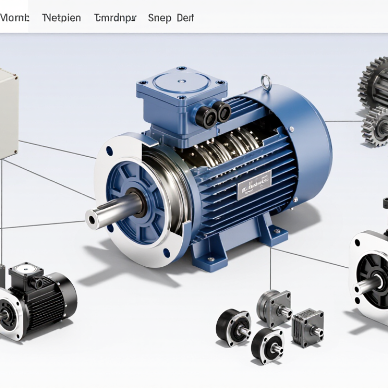
Table of Contents [Hide]
What a Motor Mount Does in an Application
What a Motor Mount Does in an Application
At its simplest, a motor mount holds the motor in a defined position. It transfers operating loads into the machine frame. That matters. A loose or overly flexible mount can let the motor shift, disturb shaft alignment, and increase vibration in nearby components. Some mounts also help limit the vibration and noise passed into a supporting structure. Their effectiveness depends on the motor, the load, and the operating conditions. No mount can solve every vibration problem.
Consider a motor driving a pump on a steel skid. The mount must support the motor’s weight and resist forces created during operation and startup. Speed, torque, load direction, temperature, and duty cycle all influence the choice. A rigid mount may help maintain alignment, while a resilient mount may reduce transmitted vibration.
One detail is easy to overlook: a softer mount can allow more movement than the connected equipment tolerates. It is also worth checking the frame and fasteners; a suitable mount cannot compensate for a flexible base or poor alignment. Real operating conditions may differ from initial estimates, so periodic checks for looseness, cracking, or unusual movement can reveal problems early.