- Home
- A-Z Catalogue
- Products
- Valves
- Cetop
- Manual Directional Valves
- Proportional Valves
- Poppet Valves
- High-Speed Linear Servo Valves
- All High-Speed Linear Servo Valves
- Cetop 10 (NG32) Two Stage Type High Speed Linear Servo Valves – LSVHG-10
- Cetop 10 (NG32) Two Stage Type High Speed Linear Servo Valves – LSVHG-10 (With Fail-Safe)
- Cetop 8 (NG25) Two Stage Type High Speed Linear Servo Valves – LSVHG-06
- Cetop 8 (NG25) Two Stage Type High Speed Linear Servo Valves – LSVHG-06 (With Fail-Safe)
- Cetop 7 (NG16) Two Stage Type High Speed Linear Servo Valves – LSVHG-04
- Cetop 7 (NG16) Two Stage Type High Speed Linear Servo Valves – LSVHG-04 (With Fail-Safe)
- Cetop 5 (NG10) Direct Type High Speed Linear Servo Valves – LSVG-03
- Cetop 5 (NG10) OBE Type Direct Operated Linear Servo Valves – LSVG-03-EH
- Cetop 3 (NG6) OBE Type Direct Operated Linear Servo Valves – LSVG-01-EH
- Pumps
- Pressure control
- Flow Control Valves
- Pressure Control Valves
- All Pressure Control Valves
- Brake Valves
- Direct Relief Valve
- Low Noise Solenoid Controlled Relief Valves
- Low Noise Pilot Operated Relief Valves
- Pilot Operated Relief Valves
- Pressure reducing and relieving valves
- Pressure reducing and check valves
- Pressure control valves
- Remote Control Relief Valves
- Solenoid Controlled Relief Valves – BSG
- Solenoid Controlled Relief Valves – BST
- Unloading relief valves
- Check valves
- Environmental
- Valves
- Hydraulic Systems
- Power pack
- About Us
- Contact
- Blog

How to Choose a Line Boring Machine?
Choosing a Line Boring Machine is not simply a matter of selecting the largest model or the lowest price. The right machine must suit the repair, the workpiece, and the conditions at the job site. A portable unit may fit a damaged excavator linkage in the field, while a workshop setup may better handle larger components and repeat jobs. Measure twice.
Start by checking the bore diameter, required boring length, material, and available clearance. These details help determine the boring bar size, mounting method, and machine capacity. Also consider how the unit will be aligned and secured. A setup that shifts under load can affect the finished bore, even when the machine itself is well built. Access matters, too: guards, nearby structures, and awkward workpiece positions can make an otherwise suitable machine difficult to use.
Compare spindle speed, feed control, power requirements, and the availability of tooling and support. Ask suppliers for clear specifications, operating guidance, and examples relevant to your type of work. Verify important claims rather than relying on a product photograph or a broad capacity figure. If possible, review a demonstration or run a test on representative material. No checklist removes every uncertainty. Job conditions vary, and the first choice may not be perfect. A careful comparison, however, can reduce avoidable downtime and help you select a Line Boring Machine that fits both current repairs and realistic future needs.
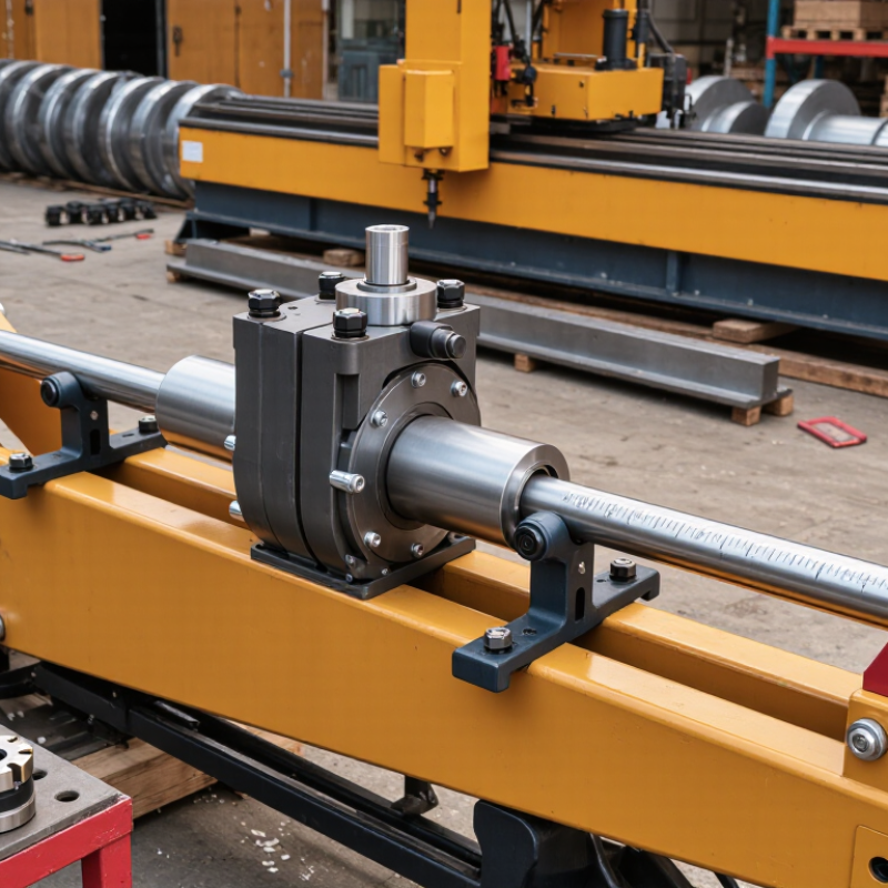
Table of Contents [Hide]
Define the Bore Repair Requirements
Before choosing a line boring machine, define the repair—not just the largest bore size. Record the damaged bore’s original diameter, required finished diameter, length, and location. Note the workpiece material and whether the bore is blind or passes through. These details affect bar length, cutting tools, and setup options. Measure carefully. A few millimeters of access can change which mounting arrangement will fit.
Set acceptance requirements before comparing machines. Specify the allowable diameter variation, surface finish, and alignment with nearby bores or shafts. Check whether the repair must happen in place, since removing a large component may be impractical. Also assess clearance for the boring bar, supports, power unit, and chip removal. A common planning mistake is focusing on diameter while overlooking setup space. The measurements may still be incomplete; verify critical dimensions on the actual workpiece.
Tips: Photograph the bore and surrounding structure, then sketch its dimensions and access limits. Ask the repair team to confirm tolerances and measurement methods. Keep a margin for tool reach and secure mounting. A machine that meets the nominal bore range may still be unsuitable if it cannot be aligned or supported safely.