- Home
- A-Z Catalogue
- Products
- Valves
- Cetop
- Manual Directional Valves
- Proportional Valves
- Poppet Valves
- High-Speed Linear Servo Valves
- All High-Speed Linear Servo Valves
- Cetop 10 (NG32) Two Stage Type High Speed Linear Servo Valves – LSVHG-10
- Cetop 10 (NG32) Two Stage Type High Speed Linear Servo Valves – LSVHG-10 (With Fail-Safe)
- Cetop 8 (NG25) Two Stage Type High Speed Linear Servo Valves – LSVHG-06
- Cetop 8 (NG25) Two Stage Type High Speed Linear Servo Valves – LSVHG-06 (With Fail-Safe)
- Cetop 7 (NG16) Two Stage Type High Speed Linear Servo Valves – LSVHG-04
- Cetop 7 (NG16) Two Stage Type High Speed Linear Servo Valves – LSVHG-04 (With Fail-Safe)
- Cetop 5 (NG10) Direct Type High Speed Linear Servo Valves – LSVG-03
- Cetop 5 (NG10) OBE Type Direct Operated Linear Servo Valves – LSVG-03-EH
- Cetop 3 (NG6) OBE Type Direct Operated Linear Servo Valves – LSVG-01-EH
- Pumps
- Pressure control
- Flow Control Valves
- Pressure Control Valves
- All Pressure Control Valves
- Brake Valves
- Direct Relief Valve
- Low Noise Solenoid Controlled Relief Valves
- Low Noise Pilot Operated Relief Valves
- Pilot Operated Relief Valves
- Pressure reducing and relieving valves
- Pressure reducing and check valves
- Pressure control valves
- Remote Control Relief Valves
- Solenoid Controlled Relief Valves – BSG
- Solenoid Controlled Relief Valves – BST
- Unloading relief valves
- Check valves
- Environmental
- Valves
- Hydraulic Systems
- Power pack
- About Us
- Contact
- Blog

How to Choose the Best Blade Antenna for UAVs?
Choosing the right antenna can shape a UAV’s communication reliability, range, and flight performance. A Blade Antenna For Uav may suit a compact airframe, but its shape alone does not guarantee a strong link. Frequency band, polarization, gain, and radiation pattern all affect how well it performs in the air. Small mismatches matter.
This guide explains how to compare blade antennas against a UAV’s radio system and operating needs. It looks at connector type, cable loss, antenna weight, mounting position, and clearance from carbon-fiber structures or other electronics. A few millimeters can change the fit. The best choice depends on the complete installation, not a product label or a headline gain figure.
Reliable selection starts with verified specifications and practical checks. Compare the antenna’s stated frequency range with the transmitter and receiver, then consider the flight orientation and expected link direction. Review manufacturer data, and test the installed system under controlled conditions before relying on it in the field. Results can vary with the airframe and setup. That is worth remembering. No single antenna is ideal for every UAV, and published figures may not reflect real flight conditions. By weighing measurable performance against weight, durability, and mounting constraints, readers can make a more informed choice and avoid preventable signal problems.
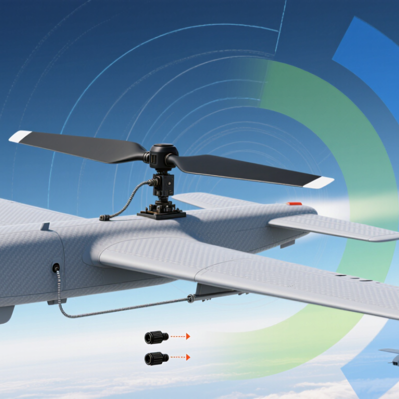
Table of Contents [Hide]
Understanding Blade Antennas and Their Role in UAVs
Blade antennas are low-profile radiators that can suit UAVs where a tall whip may snag during handling or flight. Their shape alone does not guarantee good performance. Many designs rely on a conductive ground plane, and the airframe can change the antenna’s tuning and radiation pattern. Carbon-fiber panels are especially worth checking because they can obstruct or detune nearby radiators.
On a UAV, blade antennas may carry command, telemetry, or navigation signals, depending on their frequency and design. Placement matters: mounting one close to a battery, motor, or metal fastener can affect the link. Keep its active element clear of obstructions, then test the installed aircraft—not just the antenna on a bench. Small details count. A tilted antenna can also create polarization mismatch when the aircraft banks.
The FAA’s 2024 UAS registration statistics report roughly 1.2 million registered drones in the United States, reflecting the range of platforms that need dependable radio links. That figure does not predict any individual aircraft’s requirements. Match the antenna’s operating band, connector, and polarization to the radio system, and compare measured gain and radiation-pattern data. One practical weakness remains: a blade that fits neatly may still perform poorly in the final airframe.