


- Home
- A-Z Catalogue
- Products
- Valves
- Cetop
- Manual Directional Valves
- Proportional Valves
- Poppet Valves
- High-Speed Linear Servo Valves
- All High-Speed Linear Servo Valves
- Cetop 10 (NG32) Two Stage Type High Speed Linear Servo Valves – LSVHG-10
- Cetop 10 (NG32) Two Stage Type High Speed Linear Servo Valves – LSVHG-10 (With Fail-Safe)
- Cetop 8 (NG25) Two Stage Type High Speed Linear Servo Valves – LSVHG-06
- Cetop 8 (NG25) Two Stage Type High Speed Linear Servo Valves – LSVHG-06 (With Fail-Safe)
- Cetop 7 (NG16) Two Stage Type High Speed Linear Servo Valves – LSVHG-04
- Cetop 7 (NG16) Two Stage Type High Speed Linear Servo Valves – LSVHG-04 (With Fail-Safe)
- Cetop 5 (NG10) Direct Type High Speed Linear Servo Valves – LSVG-03
- Cetop 5 (NG10) OBE Type Direct Operated Linear Servo Valves – LSVG-03-EH
- Cetop 3 (NG6) OBE Type Direct Operated Linear Servo Valves – LSVG-01-EH
- Pumps
- Pressure control
- Flow Control Valves
- Pressure Control Valves
- All Pressure Control Valves
- Brake Valves
- Direct Relief Valve
- Low Noise Solenoid Controlled Relief Valves
- Low Noise Pilot Operated Relief Valves
- Pilot Operated Relief Valves
- Pressure reducing and relieving valves
- Pressure reducing and check valves
- Pressure control valves
- Remote Control Relief Valves
- Solenoid Controlled Relief Valves – BSG
- Solenoid Controlled Relief Valves – BST
- Unloading relief valves
- Check valves
- Environmental
- Valves
- Hydraulic Systems
- Power pack
- About Us
- Contact
- Blog

How to Choose an Electrofusion Reducing Tee in 2026?
Choosing an Electrofusion Reducing Tee in 2026 requires more than comparing prices or outlet sizes. The U.S. Environmental Protection Agency’s 7th Drinking Water Infrastructure Needs Survey estimates $625 billion in drinking water investment needs over the next 20 years. Aging networks will demand fittings that support safe repairs, controlled branching, and long service life. The fitting may be small. Its consequences are not.
A reliable selection begins with the pipe system, not the catalog page. Confirm the polyethylene grade, outside diameter, SDR, pressure class, and branch dimensions. ISO 4427-3 provides requirements for polyethylene fittings used in water applications. ASTM F1055 covers electrofusion-type polyethylene fittings and offers another important technical reference. The Plastics Pipe Institute’s Handbook of Polyethylene Pipe also emphasizes compatibility, surface preparation, fusion control, and cooling time. These details affect joint strength.
Look closely at traceability. A suitable tee should carry clear identification, fusion parameters, material information, and dimensional data. Check whether the manufacturer validates performance through recognized testing. On site, scraping depth, contamination, ambient temperature, generator stability, and clamp alignment can change the result. Small errors matter. A neat-looking joint can still be weak.
This guide will examine how to choose an Electrofusion Reducing Tee for municipal, industrial, and utility projects in 2026. It will compare design requirements, standards, installation risks, supplier evidence, and lifecycle value. Some project assumptions may prove wrong. That is worth acknowledging. Careful selection improves when engineers question convenient specifications instead of accepting them blindly.
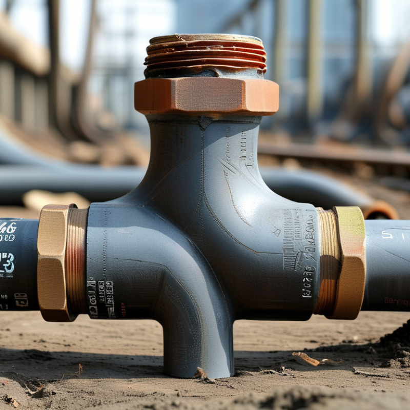
Table of Contents [Hide]
What Is an Electrofusion Reducing Tee and How Does It Work?
An electrofusion reducing tee is a polyethylene fitting with three outlets, including one smaller branch. Its built-in resistance wires create controlled heat around the pipe surface. The softened polyethylene then bonds with the fitting during cooling. No flame is used.
ISO 12176-2 covers electrofusion equipment, electrical control, and fusion procedures. In practice, the installer must scrape oxidation, remove moisture, clamp the pipes, and respect the cooling time. Small contamination can cause a hidden leak. A perfect-looking joint can still fail. That detail deserves more attention.
When choosing one in 2026, check the pipe diameter, SDR rating, pressure class, and resin compatibility. Confirm that the tee supports the required service temperature. A barcode or fusion record also improves traceability. The OECD Global Plastics Outlook projects global plastic waste to nearly triple by 2060. Reliable joints can reduce replacement work and wasted material, although durability depends on installation quality. I would not select a tee by price alone. The fitting must match the pipe system, fusion machine, and approved procedure. For critical water or gas work, verify certificates, dimensional tolerances, and test records before installation.





