- Home
- A-Z Catalogue
- Products
- Valves
- Cetop
- Manual Directional Valves
- Proportional Valves
- Poppet Valves
- High-Speed Linear Servo Valves
- All High-Speed Linear Servo Valves
- Cetop 10 (NG32) Two Stage Type High Speed Linear Servo Valves – LSVHG-10
- Cetop 10 (NG32) Two Stage Type High Speed Linear Servo Valves – LSVHG-10 (With Fail-Safe)
- Cetop 8 (NG25) Two Stage Type High Speed Linear Servo Valves – LSVHG-06
- Cetop 8 (NG25) Two Stage Type High Speed Linear Servo Valves – LSVHG-06 (With Fail-Safe)
- Cetop 7 (NG16) Two Stage Type High Speed Linear Servo Valves – LSVHG-04
- Cetop 7 (NG16) Two Stage Type High Speed Linear Servo Valves – LSVHG-04 (With Fail-Safe)
- Cetop 5 (NG10) Direct Type High Speed Linear Servo Valves – LSVG-03
- Cetop 5 (NG10) OBE Type Direct Operated Linear Servo Valves – LSVG-03-EH
- Cetop 3 (NG6) OBE Type Direct Operated Linear Servo Valves – LSVG-01-EH
- Pumps
- Pressure control
- Flow Control Valves
- Pressure Control Valves
- All Pressure Control Valves
- Brake Valves
- Direct Relief Valve
- Low Noise Solenoid Controlled Relief Valves
- Low Noise Pilot Operated Relief Valves
- Pilot Operated Relief Valves
- Pressure reducing and relieving valves
- Pressure reducing and check valves
- Pressure control valves
- Remote Control Relief Valves
- Solenoid Controlled Relief Valves – BSG
- Solenoid Controlled Relief Valves – BST
- Unloading relief valves
- Check valves
- Environmental
- Valves
- Hydraulic Systems
- Power pack
- About Us
- Contact
- Blog

China Best Alkaline Water Hydrogen Production Equipment?
Choosing the best Alkaline Water Hydrogen Production Equipment depends less on a headline capacity and more on the demands of the intended application. A system that suits a pilot facility may not fit continuous industrial operation. The right comparison starts with verified hydrogen output, operating pressure, product purity, energy consumption, and expected duty cycle.
An alkaline water electrolysis system typically brings together an electrolyzer, power supply, water treatment, gas separation, cooling, and control equipment. Each part affects installation and operation. For example, check whether the quoted production rate applies at the stated pressure and operating conditions. Compare water-quality requirements, utility connections, floor space, maintenance access, and the supplier’s service arrangements. Small details matter.
Specifications can look similar on paper. They may describe different test conditions, so ask suppliers to explain their figures and provide supporting documentation. A practical assessment should also consider commissioning support, replacement-part availability, monitoring features, and procedures for handling routine maintenance. These checks help buyers judge both performance and long-term fit.
There is no universal winner. The strongest choice is the equipment that meets documented process requirements and can be supported reliably at the site. Some purchasing decisions still rely too heavily on initial price; that deserves a second look. A qualified engineering review can clarify trade-offs before a final selection.
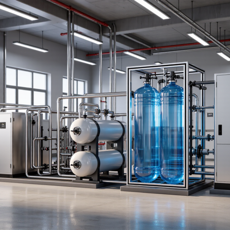
Table of Contents [Hide]
What Alkaline Water Hydrogen Production Equipment Is
What Is Alkaline Water Hydrogen Production Equipment?
Alkaline water hydrogen production equipment uses electricity to split water into hydrogen and oxygen. Its electrolyzer stack contains electrodes separated by a porous diaphragm and an alkaline liquid electrolyte. The diaphragm helps keep the gases apart while ions move through the liquid. That is the core.
A complete system usually includes the stack, a power supply, water treatment, cooling, gas-liquid separators, and controls. Hydrogen may also pass through purification and drying equipment before use. On a practical skid, pipes, valves, and sensors manage water flow, temperature, pressure, and gas quality. Operators monitor these readings because uneven flow or heat can affect stable operation. The term “alkaline water” can confuse buyers: this is industrial hydrogen equipment, not a drinking-water appliance.
The International Energy Agency’s Global Hydrogen Review 2024 reported 1.4 GW of water-electrolyser capacity installed worldwide by the end of 2023. That figure shows the technology’s growing deployment, but it does not guarantee that every unit performs equally well. Buyers should compare rated output with operating conditions, energy use, hydrogen purity, and maintenance needs. A specification sheet rarely tells the whole story. Feedwater quality and real operating hours matter, too.