7 Best Hydraulic Pressure Relief Valves for Buyers

Choosing a hydraulic pressure relief valve is less about chasing the highest rating and more about protecting a real circuit. A press, lift, or compact power unit each places different demands on its valve. Pump flow, operating pressure, duty cycle, and fluid compatibility all matter. One mismatch can cause excess heat, nuisance opening, or unstable pressure. Small details matter.

Hydraulic-control author John Watton’s work points to a practical buying principle, paraphrased here: “Match pressure-control components to the circuit’s actual operating conditions, not just its headline rating.” That is useful guidance, though no single rule replaces checking the equipment manufacturer’s specifications. Compare setting range, flow capacity, response, connection size, adjustment method, and service access. A valve that fits the pressure range may still be a poor choice if its flow capacity is inadequate.

This guide reviews seven hydraulic pressure relief valve options for different buyer needs, from straightforward systems to demanding applications. We consider construction, adjustment features, installation requirements, and the information buyers should verify before ordering. A ranked list can make selection seem tidy. Real systems are messier. Confirm the operating limits and compatibility details for your own circuit before choosing.
7 Best Hydraulic Pressure Relief Valves for Buyers

Hydraulic Pressure Relief Valves: Purpose and Operating Principles

Hydraulic pressure relief valves limit pressure when pump flow meets resistance, protecting cylinders, hoses, and other components from overload. In a common spring-loaded design, system pressure acts on a poppet or spool. Once force overcomes the spring setting, the valve opens and diverts excess oil toward the tank. As pressure falls, the spring pushes it closed. That matters.

Valve response depends on more than its set pressure. Flow capacity, oil temperature, contamination, and back pressure can affect pressure rise and stability. ISO 3448 classifies ISO VG 46 oil at 40°C as 41.4–50.6 mm²/s; viscosity outside the intended range can change valve response. ISO 4413:2010 sets safety requirements for hydraulic systems, including protection against pressure exceeding permissible limits. A relief valve is not a substitute for correctly sizing the pump, lines, and actuators. One detail is easy to miss: a valve may protect the circuit yet still waste energy if it bypasses flow continuously.

Tips: Set pressure with a calibrated gauge while the oil is near operating temperature. Check the valve’s rated flow, then inspect for leakage, noise, or pressure drift. Small checks help.

Common Types of Hydraulic Pressure Relief Valves

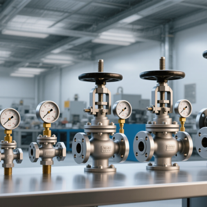
Hydraulic pressure relief valves generally fall into direct-acting, pilot-operated, and proportional types. Direct-acting valves use a spring-loaded poppet or spool. When inlet pressure overcomes spring force, the valve opens and diverts oil to the tank. Their simple construction suits compact circuits and quick protection. Pilot-operated valves use a smaller pilot stage to control a main valve. They are often selected for higher flow rates and steadier pressure control. Proportional valves adjust the relief setting through an electrical signal, useful when operating conditions change during a machine cycle. Small but important: response, flow capacity, and pressure stability vary by design.

Selection needs more than a pressure rating. Check the system’s maximum flow, fluid viscosity, port size, and expected temperature; then compare the valve’s pressure-flow curve. ISO 4413:2010 provides safety requirements for hydraulic systems, including protection against excessive pressure. Grand View Research’s hydraulic equipment market report estimated the global market at about US$44 billion in 2022, reflecting the scale of equipment that depends on reliable pressure control. That figure covers the wider equipment market, not relief valves alone. A common buying mistake is choosing by nominal pressure only. The “right” type can still behave poorly if its setting, installation, or return-line conditions do not match the circuit.

7 Best Hydraulic Pressure Relief Valves for Buyers - Common Types of Hydraulic Pressure Relief Valves

Valve type How it works Common applications Main advantages Buyer considerations
Direct-acting poppet System pressure acts directly on a spring-loaded poppet. The poppet opens when pressure overcomes the spring force. Compact hydraulic power units, branch circuits, and applications needing a straightforward pressure limit. Simple construction, fast response, and reliable operation in compact circuits. Confirm rated flow and pressure range. At higher flow, pressure may rise above the initial opening setting.
Direct-acting ball A spring holds a ball against a seat; pressure lifts the ball to open a path to the return line. Small circuits, low-flow protection, and applications where a simple, economical valve is suitable. Few moving parts and a simple design that is easy to understand and install. Check allowable leakage, flow capacity, and pressure stability; a ball-seat design may not suit every high-flow or precision-control duty.
Pilot-operated A small pilot stage controls pressure in the main valve chamber, allowing the main element to handle the larger flow. Higher-flow systems, industrial hydraulic circuits, and systems that need more stable pressure control over a broad flow range. Often offers better pressure control at higher flow and lower pressure override than a comparable direct-acting design. Requires clean fluid and correct drain or pilot-line arrangements where specified. Verify minimum operating flow and installation requirements.
Solenoid-controlled, ventable relief A solenoid-operated stage vents or changes pilot pressure so the system can switch between pressure states or unload, depending on the circuit design. Machines needing electrically controlled unloading, remote pressure switching, or a low-pressure standby mode. Allows electrical control of pressure functions without relying only on manual adjustment. Check the solenoid voltage, control logic, fail-safe state, and whether the circuit needs a separate directional or unloading valve.
Proportional pressure relief An electrical input varies the valve's pressure setting, usually through a proportional solenoid acting on the valve mechanism. Mobile machinery and industrial systems that require adjustable pressure settings or automated pressure control. Supports remote and continuously variable pressure commands within the valve's specified operating range. Confirm the required driver or amplifier, command signal, pressure range, response, and fail-safe behavior. It does not replace circuit-level safety design.
Cross-port shock relief One or more relief elements connect a hydraulic motor's work ports to limit pressure spikes; some designs include makeup check valves. Hydraulic motors exposed to sudden load changes, overrunning loads, or pressure shocks. Provides local protection against transient pressure in the motor circuit; makeup checks can help address low-pressure conditions. Match the valve to motor flow, port configuration, pressure setting, and circuit layout. It is not a substitute for the main system relief valve.
Thermal relief A small relief valve opens when fluid trapped in a closed section expands as its temperature rises. Isolated cylinders, blocked-in lines, and other fluid volumes that can be exposed to heat. Protects trapped sections from pressure increases caused by thermal expansion. Select for the protected volume and discharge route. It is intended for limited thermal-expansion flow, not as the main system pressure-control valve.

Selection note: Pressure settings, flow capacity, allowable back pressure, fluid compatibility, and installation requirements vary by valve design. Verify these values against the valve specification and the hydraulic circuit design.

Key Factors for Choosing a Relief Valve

Choosing a hydraulic pressure relief valve starts with the system’s real operating conditions, not just the pump label. Record normal pressure, peak pressure, expected flow, and fluid temperature. A valve set too low may open during ordinary work; one set too high may leave hoses and components exposed to damaging pressure. Small margins matter.

Check the valve’s rated flow at the pressure difference your circuit can provide. A compact valve may fit neatly on a manifold but still struggle when a cylinder moves quickly. Also consider response stability, allowable backpressure, and whether a direct-acting or pilot-operated design suits the circuit. Review the manufacturer’s pressure-flow data rather than relying on port size alone.

Fluid compatibility deserves equal attention. Seal and body materials must suit the hydraulic fluid, temperature range, and likely contamination level. Think about access, too: can a technician reach the adjustment screw and inspect the valve without removing nearby lines? In practice, the “ideal” choice may change after measuring a warm machine under load. That is an awkward detail, but it is better to verify the setting with suitable gauges and qualified procedures than to trust an old note in the maintenance log.

Seven Hydraulic Pressure Relief Valves for Buyers to Compare

A useful comparison starts with the circuit, not the catalog. Direct-acting relief valves respond quickly and suit simpler, lower-flow systems. Pilot-operated valves can handle higher flow with less pressure variation. Adjustable models let technicians set opening pressure, while fixed-setting designs reduce accidental adjustment. Cartridge valves fit compact blocks and are easier to replace. Manifold-mounted valves simplify tight hydraulic assemblies. Proportional relief valves allow pressure control through an electrical signal. Thermal relief valves protect trapped fluid from heat expansion; they are not substitutes for a main system valve. Small details matter.

Tips: Compare rated flow, pressure range, response behavior, port size, and fluid compatibility. Check the specified setting against the machine’s operating pressure, not just its maximum rating. A gauge reading at rest may not reveal pressure spikes during movement.

Installation affects performance. Keep return paths clear, use clean fluid, and follow the valve maker’s stated mounting direction and torque values. A valve that chatters may indicate an unsuitable setting, contamination, or an unstable circuit, so replacing it immediately may not solve the cause. Buyers should also consider adjustment access and service intervals. A neat comparison table can still miss one awkward fitting or an unexpected temperature range; that is worth checking before purchase.

7 Hydraulic Pressure Relief Valve Types to Compare

Indicative adjustable pressure-setting ranges (bar)

Pressure ranges are broad, representative engineering bands—not guaranteed specifications. Actual limits depend on the valve design, size, fluid, and operating conditions. Check the product datasheet and system requirements before selecting a valve.

Installation, Adjustment, and Maintenance Basics

A pressure relief valve protects a hydraulic circuit only when its installation matches the system design. Check the valve’s pressure rating, flow capacity, and port markings against the machine specifications. Mount it in the correct direction, with clean fittings and minimal restrictions in the discharge line. Keep the return path clear. Even a small blockage can affect pressure response. Before installation, remove dirt from hoses and ports; one grit particle may damage a sealing surface.

Adjustment should be measured, not guessed. Fit a suitable pressure gauge near the valve, run the system under the specified conditions, and increase the setting in small steps. Never exceed the lowest pressure rating of connected components. Secure the adjustment mechanism after testing, then record the final setting. In practice, a tidy schematic can hide pressure spikes or changing loads, so verify performance during realistic operation. A quiet valve is not proof of a safe setting.

For maintenance, inspect for leaks, loose connections, unusual noise, and pressure drift. Check fluid condition and replace filters according to the equipment schedule. If the setting changes repeatedly, investigate contamination, wear, or an undersized valve rather than tightening the adjuster indefinitely. Depressurize the circuit before servicing; trapped pressure can remain after shutdown. Keep clear records. Small details matter.