- Home
- A-Z Catalogue
- Products
- Valves
- Cetop
- Manual Directional Valves
- Proportional Valves
- Poppet Valves
- High-Speed Linear Servo Valves
- All High-Speed Linear Servo Valves
- Cetop 10 (NG32) Two Stage Type High Speed Linear Servo Valves – LSVHG-10
- Cetop 10 (NG32) Two Stage Type High Speed Linear Servo Valves – LSVHG-10 (With Fail-Safe)
- Cetop 8 (NG25) Two Stage Type High Speed Linear Servo Valves – LSVHG-06
- Cetop 8 (NG25) Two Stage Type High Speed Linear Servo Valves – LSVHG-06 (With Fail-Safe)
- Cetop 7 (NG16) Two Stage Type High Speed Linear Servo Valves – LSVHG-04
- Cetop 7 (NG16) Two Stage Type High Speed Linear Servo Valves – LSVHG-04 (With Fail-Safe)
- Cetop 5 (NG10) Direct Type High Speed Linear Servo Valves – LSVG-03
- Cetop 5 (NG10) OBE Type Direct Operated Linear Servo Valves – LSVG-03-EH
- Cetop 3 (NG6) OBE Type Direct Operated Linear Servo Valves – LSVG-01-EH
- Pumps
- Pressure control
- Flow Control Valves
- Pressure Control Valves
- All Pressure Control Valves
- Brake Valves
- Direct Relief Valve
- Low Noise Solenoid Controlled Relief Valves
- Low Noise Pilot Operated Relief Valves
- Pilot Operated Relief Valves
- Pressure reducing and relieving valves
- Pressure reducing and check valves
- Pressure control valves
- Remote Control Relief Valves
- Solenoid Controlled Relief Valves – BSG
- Solenoid Controlled Relief Valves – BST
- Unloading relief valves
- Check valves
- Environmental
- Valves
- Hydraulic Systems
- Power pack
- About Us
- Contact
- Blog

Who Is the Best BESS Connector Supplier in China?
China’s battery energy storage market is expanding quickly, making connector selection a practical reliability decision—not a minor purchasing detail. The National Energy Administration reported that China’s new-type energy storage capacity reached 73.76 GW by the end of 2024, up about 130% from a year earlier. Behind those figures are real installations: battery racks, power conversion systems, and connections exposed to heat, vibration, and repeated service work.
The International Energy Agency’s Batteries and Secure Energy Transitions report says global energy storage capacity needs to grow sixfold by 2030 in its net-zero pathway. IEA Executive Director Fatih Birol has described batteries as “a critical technology for clean energy transitions.” That broader point matters at the connector level. A poorly specified Bess Connector can add resistance, complicate maintenance, or create avoidable downtime. Small part. Large consequences.
So, who is the best BEss Connector supplier in China? There is no credible answer based on price or a polished catalogue alone. Buyers should compare current ratings, contact resistance, locking design, material traceability, test documentation, and support for system integration. Ask for evidence from the actual product family—not just general company claims. A sample that fits neatly on a bench may behave differently inside a hot container after years of cycling. That deserves scrutiny.
This introduction sets up a supplier comparison grounded in measurable performance, manufacturing consistency, and service capability. It also leaves room for doubt: public data rarely reveals how every connector performs in the field. That gap matters.
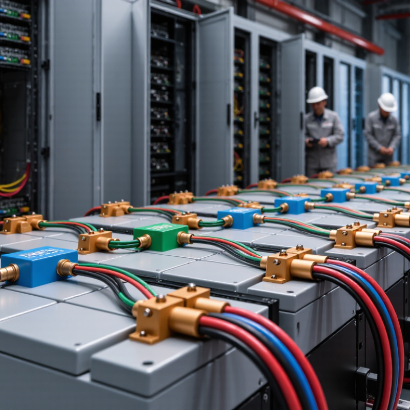
Table of Contents [Hide]
China’s BESS Connector Landscape: 1,500 V DC Systems and Key Interfaces
China’s BESS connector market is shaped by larger battery installations and higher-voltage designs. At 1,500 V DC, connectors must handle insulation demands, thermal loads, and safe maintenance access. The International Energy Agency reported that global battery storage additions more than doubled in 2023, reaching about 42 GW. Its 2024 Batteries and Secure Energy Transitions report estimates installed capacity at roughly 85 GW. These figures show the sector’s scale, but do not directly measure connector demand.
Key interfaces include battery rack-to-busbar links, battery-to-power-conversion-system connections, and auxiliary signal wiring. Each has different requirements. A DC power connector needs secure contact pressure and controlled temperature rise; a signal interface must resist vibration and maintain reliable sensing. Small parts matter. One overlooked issue is service access: technicians need enough clearance to inspect and replace connections inside tightly packed containers.
For buyers comparing suppliers in China, request test records for contact resistance, temperature rise, mating cycles, and ingress protection. Confirm that ratings apply to the intended cable size and operating conditions, not just a laboratory sample. Ask how polarity protection and locking features work with gloved hands. Paper specifications help, but they do not reveal every installation difficulty. A trial assembly can expose awkward cable bends before a project reaches the field.
Who Is the Best BESS Connector Supplier in China? — China’s BESS Connector Landscape: 1,500 V DC Systems and Key Interfaces
There is no single best supplier for every battery energy storage system (BESS). The right choice depends on the system architecture, electrical ratings, installation method, environmental conditions, and documented qualification of the complete connection system.
| BESS interface | Typical connection approach | What to specify for a 1,500 V DC design | Key evaluation points |
|---|---|---|---|
| Cell-to-module interconnection | Welded, bolted, or purpose-designed internal conductive links; the construction depends on cell and module design. | Module voltage and current, conductor material and dimensions, joint method, insulation, and assembly process. | Joint resistance, temperature rise, vibration durability, corrosion compatibility, and repeatable manufacturing quality. |
| Module or rack power connection | Touch-protected plug-in connectors, bolted terminals, or other keyed connections designed for the battery enclosure. | Maximum operating voltage, rated current, polarity, cable or busbar compatibility, allowable temperature range, and mating-cycle requirements. | Protection against accidental contact, incorrect mating, loosening, overheating, and exposure to dust or moisture. |
| Rack-to-DC collection connection | Insulated power cables with suitable terminals or a designed busbar system, depending on layout and current distribution. | System maximum voltage, branch and aggregate current, conductor cross-section, fault-current conditions, and installation clearances. | Short-circuit withstand, insulation coordination, terminal temperature rise, cable routing, and accessibility for maintenance. |
| DC collection to power conversion system (PCS) | Bolted busbar terminals, cable lugs, or manufacturer-specified high-current terminals at the DC interface. | PCS input voltage window, continuous and transient current, terminal arrangement, conductor size, and required isolation provisions. | Compatibility with the PCS terminal design, connection torque, thermal performance, fault protection, and service access. |
| Battery management and interlock signals | Low-voltage signal connectors or terminal blocks for monitoring, communication, sensing, and interlock circuits. | Signal type, pin assignment, voltage and current limits, shielding, grounding, and separation from power wiring. | Clear pinout documentation, vibration retention, electromagnetic compatibility, environmental sealing, and reliable fault detection. |
| Enclosure cable entry and feed-throughs | Cable glands, sealed feed-throughs, or connector panels selected for the enclosure and cable arrangement. | Cable diameter, enclosure material, required ingress protection, strain relief, and any bonding or grounding requirements. | Seal integrity after installation, mechanical retention, corrosion resistance, and compatibility with the enclosure’s declared protection level. |
| Supplier qualification | Review the proposed connector, cable, terminal, tooling, and assembly instructions as a complete connection solution. | Obtain ratings for the exact part and configuration; do not infer voltage or current capability from appearance or another product in the range. | Traceable test reports, material and process controls, change notification, sample availability, and technical support for the target application. |
Standards and rating checks
| Reference or rating | How to use it |
|---|---|
| 1,500 V DC system rating | Treat 1,500 V DC as the system design maximum only where specified by the project. Verify that every connector and associated component is rated for the actual maximum voltage and installation conditions. |
| IEC 60529 ingress protection (IP) code | Use the declared IP rating to assess protection against access, solid objects, and water. Check whether the rating applies to the assembled connector in its intended mated or unmated state. |
| IEC 61984 | This standard addresses safety requirements and tests for connectors within its scope. Confirm the product’s applicable standard and certification documentation rather than assuming applicability from a marketing statement. |
| IEC 62852 | This standard covers connectors for DC application in photovoltaic systems. It may be relevant to a connector used in a PV-related application, but it does not automatically establish suitability for every BESS interface. |
| IEC 62619 | This standard addresses safety requirements for industrial lithium batteries and battery systems. It is not, by itself, a connector product rating. |
| Rated current and temperature rise | Current capacity is product- and installation-specific. Check the manufacturer’s rating conditions, conductor size, ambient temperature, grouping, and test evidence for the selected configuration. |
Selection principle: The best supplier is the one that can substantiate the required ratings for the exact interface, provide complete and traceable technical documentation, and support installation and quality control for the project. Verify all ratings against the current datasheet, applicable standards, and system design.