


- Home
- A-Z Catalogue
- Products
- Valves
- Cetop
- Manual Directional Valves
- Proportional Valves
- Poppet Valves
- High-Speed Linear Servo Valves
- All High-Speed Linear Servo Valves
- Cetop 10 (NG32) Two Stage Type High Speed Linear Servo Valves – LSVHG-10
- Cetop 10 (NG32) Two Stage Type High Speed Linear Servo Valves – LSVHG-10 (With Fail-Safe)
- Cetop 8 (NG25) Two Stage Type High Speed Linear Servo Valves – LSVHG-06
- Cetop 8 (NG25) Two Stage Type High Speed Linear Servo Valves – LSVHG-06 (With Fail-Safe)
- Cetop 7 (NG16) Two Stage Type High Speed Linear Servo Valves – LSVHG-04
- Cetop 7 (NG16) Two Stage Type High Speed Linear Servo Valves – LSVHG-04 (With Fail-Safe)
- Cetop 5 (NG10) Direct Type High Speed Linear Servo Valves – LSVG-03
- Cetop 5 (NG10) OBE Type Direct Operated Linear Servo Valves – LSVG-03-EH
- Cetop 3 (NG6) OBE Type Direct Operated Linear Servo Valves – LSVG-01-EH
- Pumps
- Pressure control
- Flow Control Valves
- Pressure Control Valves
- All Pressure Control Valves
- Brake Valves
- Direct Relief Valve
- Low Noise Solenoid Controlled Relief Valves
- Low Noise Pilot Operated Relief Valves
- Pilot Operated Relief Valves
- Pressure reducing and relieving valves
- Pressure reducing and check valves
- Pressure control valves
- Remote Control Relief Valves
- Solenoid Controlled Relief Valves – BSG
- Solenoid Controlled Relief Valves – BST
- Unloading relief valves
- Check valves
- Environmental
- Valves
- Hydraulic Systems
- Power pack
- About Us
- Contact
- Blog

7 Tips for Barite Drywall Radiation Shielding?
Radiation shielding decisions should begin with evidence, not attractive wall panels. Barite Drywall Radiation Shielding can reduce scattered X-ray exposure when designed, installed, and verified correctly. However, no single board thickness suits every room. Equipment type, workload, beam direction, occupancy, distance, and wall construction all matter.
NCRP Report No. 147 provides widely used guidance for diagnostic X-ray facility shielding design. It emphasizes workload, use factors, occupancy, and controlled dose limits. The IAEA’s Safety Reports Series No. 47 also recommends formal shielding calculations and qualified expert review. These documents support a practical lesson: product labels cannot replace a radiation protection assessment. A dense barite panel may appear substantial, yet joints, doors, ceilings, service penetrations, and poorly sealed edges can create weak points. Small gaps matter.
Real rooms reveal the risks. A busy CT suite may produce a very different shielding demand from a low-use dental room. Nearby offices, corridors, and waiting areas also require attention. The National Council on Radiation Protection and Measurements promotes optimization under the ALARA principle, keeping exposure as low as reasonably achievable without compromising clinical work. That principle should guide every tip in this article.
Some assumptions deserve challenge. Barite drywall is not automatically safer than every alternative. It may simplify installation, but its mass can affect framing, transport, and structural loading. Verification is essential. A qualified medical physicist should review drawings, calculate shielding, and support post-installation radiation surveys. These seven tips focus on practical details, credible documentation, and the mistakes that are easy to overlook. Good shielding is quiet, measurable, and deliberately engineered.
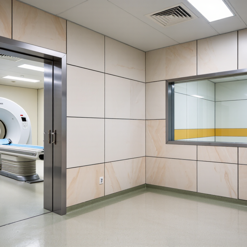
Table of Contents [Hide]
Define X-Ray Energy, Workload, Distance, and Occupancy Before Shielding Design
7 Tips for Barite Drywall Radiation Shielding
Tip 1: Define the X-ray energy before selecting barite drywall. Diagnostic systems commonly operate across approximately 40–150 kVp, and higher energies require different attenuation assumptions.
Tip 2: Confirm the workload in mA-minutes per week. NCRP Report No. 147 identifies workload as a core shielding input, not a minor estimate.
Tip 3: Separate routine workload from peak clinical demand. A busy room can change quickly.
Tip 4: Measure distance from the X-ray focal spot to nearby occupied areas. The inverse-square relationship strongly affects shielding requirements.
Tip 5: Map occupancy carefully. A continuously occupied office differs from a corridor or storage room. IAEA Safety Reports Series No. 47 recommends evaluating distance, workload, radiation energy, and occupancy together.
Tip 6: Check primary and secondary barriers separately. The wall receiving the direct beam usually needs more attention than a scatter-only partition. Small design errors become expensive later.
Tip 7: Verify the installed construction, not only the drawings. Barite board joints, penetrations, doors, and service outlets can create weak points. Field surveys should follow commissioning and altered workloads. NCRP guidance supports design goals based on the protection of workers and the public. Still, published factors are not universal answers. Local measurements, equipment specifications, and a qualified medical physicist remain necessary. I sometimes see projects over-shielded because occupancy was guessed conservatively. That protects uncertainty, but wastes usable space and budget. A documented assumption is better than a hidden one.





