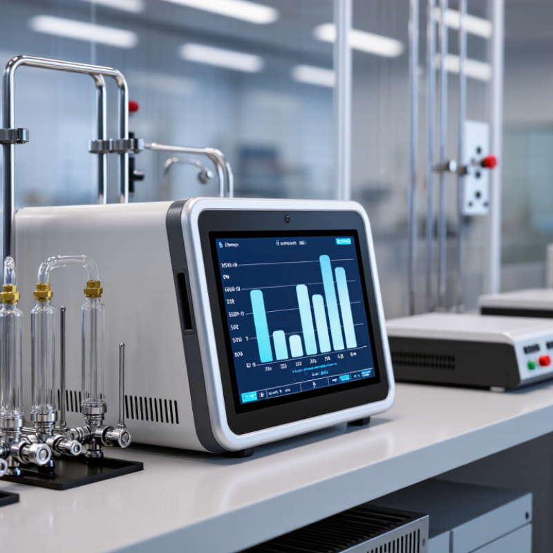
| Electrochemical Fuel-Cell Analyzer | Commonly from low ppm levels to approximately 1–5% oxygen, depending on cell design. Some specialized cells support sub-ppm measurement. | - Inert-gas blanketing
- Welding and heat-treatment gases
- Gloveboxes
- Gas-cylinder quality checks
- Portable leak and process verification
| - Use clean, dry, non-condensing sample gas.
- Install a particulate filter and pressure regulator where required.
- Control flow according to the analyzer manual; excessive flow can damage or destabilize the cell.
- Use compatible tubing, commonly stainless steel or suitably low-permeability polymer.
- Minimize dead volume and atmospheric leaks.
| - Perform a zero check with oxygen-free gas when the application requires low-ppm accuracy.
- Perform span calibration with a certified oxygen-in-nitrogen or oxygen-in-process-gas mixture.
- Use calibration gases with traceability to a national metrology institute or an ISO/IEC 17025-accredited laboratory.
- Calibration intervals are commonly quarterly to annually, based on risk, drift, and operating conditions.
| - Inspect for leaks, moisture, contamination, and filter blockage.
- Replace the sensor when response time, baseline stability, or sensitivity no longer meets the specification.
- Store replacement cells according to the manufacturer’s instructions to limit premature aging.
| - Low power consumption
- Simple operation
- Suitable for portable instruments
- Good performance at ambient temperature
- Often economical for routine trace measurements
| - Sensor life is consumable and depends on oxygen exposure.
- Strongly affected by leaks, moisture, solvents, and reactive gases.
- Response can become slow after prolonged exposure to high oxygen concentrations.
| - IEC 61010-1 for measurement and laboratory equipment safety, where applicable.
- IEC 61326-1 for electromagnetic compatibility, where applicable.
- ISO/IEC 17025 principles for calibration traceability.
- Hazardous-area certification may be required for classified locations.
|
| Zirconia or Solid-Electrolyte Analyzer | Typically from low ppm levels to percent or high-percent oxygen. Measurement performance depends strongly on cell temperature, sample composition, and design. | - Furnaces and combustion processes
- Heat-treatment atmospheres
- Boilers and flue-gas monitoring
- High-temperature process control
- Continuous industrial gas analysis
| - Install the sensor at the specified operating temperature, often several hundred degrees Celsius.
- Protect the cell from liquid water, dust, particulates, and corrosive compounds.
- Use a heated sample line where condensation is possible.
- Provide stable electrical power and adequate ventilation around heated components.
- For extractive systems, use a properly designed sample-conditioning system.
| - Use zero and span gases appropriate to the expected oxygen range.
- Allow the sensor and sample system to reach thermal equilibrium before calibration.
- Verify calibration after major process changes, sensor replacement, or sample-system work.
- Check sensor temperature and reference-air quality because both influence accuracy.
| - Inspect heaters, thermocouples, seals, filters, and sample lines.
- Remove deposits and replace damaged or aged cells.
- Check for air ingress in low-oxygen applications.
- Use a documented preventive-maintenance schedule, commonly monthly inspection with periodic performance verification.
| - Wide measurement capability
- Fast response in suitable process designs
- Continuous operation at elevated temperatures
- Useful for combustion and furnace control
| - Heated components create burn and ignition hazards.
- Not ideal for every ambient-temperature trace application.
- Combustible gases and reducing compounds may interfere or create safety risks.
- Condensation and dust can cause rapid sensor failure.
| - IEC 61010-1 and IEC 61326-1, where applicable.
- Process installation and electrical-area requirements may apply.
- Combustion and emissions installations may need to meet local environmental monitoring rules.
- Hazardous-area approval is required when installed in a classified zone.
|
| Paramagnetic Analyzer | Commonly percent-level oxygen, with selected systems capable of lower concentrations when combined with suitable sample conditioning. | - Gas blending and distribution
- Medical and industrial oxygen verification
- Air-separation processes
- Continuous process monitoring
- Laboratory and quality-control applications
| - Provide a clean, dry, stable-pressure sample.
- Prevent oil, liquid carryover, dust, and magnetic contamination.
- Install a pressure regulator, flow control, and suitable filtration.
- Ensure the sample gas temperature is within the specified range.
- Use oxygen-compatible materials and fittings where oxygen-enriched gas is measured.
| - Calibrate with certified zero and span gases covering the intended operating range.
- Verify flow and pressure before calibration.
- Check linearity at more than one concentration when the measurement is used for release or custody-quality decisions.
- Maintain calibration records and uncertainty information.
| - Inspect the sample filter and flow path.
- Check the measurement cell for contamination and mechanical stability.
- Verify zero drift and span response at a risk-based interval.
- Keep the sample system free of oil and moisture.
| - Non-consumable measurement principle
- Good repeatability for percent-level oxygen
- Low dependence on chemical sensor replacement
- Suitable for continuous monitoring
| - Usually less suitable than fuel-cell or optical technologies for ultra-low ppm oxygen.
- Water vapor, pressure, flow, and paramagnetic or diamagnetic sample components can affect results.
- Some designs contain delicate mechanical or optical components.
| - IEC 61010-1 and IEC 61326-1, where applicable.
- Medical oxygen systems may require compliance with applicable national medical-device and gas-quality regulations.
- Industrial installations may require hazardous-area and oxygen-service controls.
|
| Tunable Diode Laser Absorption Spectroscopy (TDLAS) | Application-dependent; commonly percent to ppm levels. Performance depends on optical path length, wavelength, pressure, temperature, and interference control. | - High-purity and specialty gases
- Semiconductor and electronics gas systems
- Continuous process monitoring
- Inerting and glovebox control
- Rapid measurement where minimal sample contact is preferred
| - Use a leak-tight, low-background sample system.
- Control pressure and temperature within the validated operating range.
- Prevent dust, aerosols, condensation, and window contamination.
- Use adequate purge procedures for the optical path where specified.
- Install a bypass and safe vent when the sample contains hazardous or oxygen-deficient gas.
| - Use certified reference gases or a validated comparison method.
- Verify zero and span after installation, optical-window service, or major sample-system changes.
- Perform wavelength, pressure, temperature, and interference checks according to the validated method.
- For critical applications, confirm results through an independent laboratory or reference analyzer.
| - Keep optical windows and filters clean.
- Inspect purge gas, sample flow, pressure control, and window seals.
- Review diagnostic alarms and trend data for optical fouling or drift.
- Schedule periodic verification rather than relying only on self-diagnostics.
| - Fast response
- Minimal consumable sensor components
- Good selectivity when the spectral line is properly chosen
- Can support remote and continuous monitoring
| - Higher initial cost and greater dependence on application engineering.
- Interfering gases, pressure changes, dust, and condensation can affect accuracy.
- Requires careful validation for very low concentrations.
| - IEC 61010-1 and IEC 61326-1, where applicable.
- ISO/IEC 17025 traceability is relevant for calibration gases and validation services.
- Hazardous-area certification and functional-safety requirements may apply to process installations.
|
| Ultraviolet or Visible Absorption Analyzer | Commonly percent to ppm oxygen, depending on optical path length, lamp source, and system design. | - Gas purity and process monitoring
- Combustion and emissions applications
- Continuous extractive analysis
- Applications requiring low sample contact with a sensor electrolyte
| - Use a clean and dry sample stream.
- Control sample pressure, temperature, and flow.
- Protect optical windows from condensation and particulate deposition.
- Use appropriate sample conditioning for acidic, corrosive, or wet gases.
- Provide safe exhaust and ventilation for hazardous samples.
| - Perform zero and span calibration with certified gases.
- Check lamp intensity, optical baseline, and detector response.
- Validate interference corrections where the sample contains absorbing gases.
- Record calibration uncertainty and environmental conditions.
| - Clean optical windows and replace filters when required.
- Monitor lamp aging and detector diagnostics.
- Inspect sample conditioning components for leaks and contamination.
- Confirm baseline stability during scheduled service.
| - No electrolyte-based oxygen cell replacement
- Suitable for continuous systems
- Can provide fast optical response
- Useful where chemical sensor poisoning is a concern
| - Optical fouling and lamp aging can cause drift.
- Other ultraviolet- or visible-absorbing gases may interfere.
- Sample conditioning can be more complex than for simple portable analyzers.
| - IEC 61010-1 and IEC 61326-1, where applicable.
- Local emissions-monitoring requirements may apply to stack or combustion installations.
- Use certified calibration materials with documented traceability.
|
| Residual Gas Analyzer or Mass-Spectrometric System | From ultra-trace levels to percent oxygen, depending on vacuum design, detector, gas load, and calibration method. | - Research and development
- Vacuum systems
- Semiconductor and advanced-material processing
- Leak investigation and gas-species profiling
- Applications requiring multi-component analysis
| - Requires a stable vacuum system, suitable inlet, and controlled gas load.
- Use leak-tight vacuum-compatible components.
- Protect the instrument from particulates, condensable vapors, and excessive pressure.
- Provide adequate grounding, ventilation, and protection from hazardous gases.
- Allow sufficient warm-up and stabilization time.
| - Use certified gas mixtures or a validated reference-gas system.
- Perform mass-scale, sensitivity, zero, and response checks.
- Account for background gas, fragmentation, pressure dependence, and detector aging.
- Use documented method validation for quantitative release decisions.
| - Check vacuum integrity and background levels.
- Clean or replace inlet components when contamination is detected.
- Verify detector performance, tuning, and mass calibration.
- Maintain pumps and foreline components according to operating hours and gas load.
| - Very broad analytical capability
- Can identify multiple gases in one measurement
- Suitable for demanding research and vacuum applications
- Potentially very low detection limits
| - Higher complexity and operating cost
- Requires trained personnel and a controlled installation
- Results depend strongly on vacuum conditions and quantitative calibration
- Usually unsuitable for simple field monitoring
| - IEC 61010-1 and IEC 61326-1, where applicable.
- Laboratory quality systems should address method validation, uncertainty, and calibration traceability.
- Vacuum, electrical, chemical, and hazardous-gas safety requirements must be assessed for the installation.
|